Hydronics Workshop | John Siegenthaler
Seizing Control
A simple way of keeping heat available in a dual fuel system.
Air-to-water heat pumps are different from boilers. As the outdoor air temperature decreases, their heating output decreases. That’s a characteristic of all air-source heat pumps, and it runs opposite to how heating load changes with decreasing outdoor temperature.
Considered together, these two characteristics imply that at some outdoor temperature the output of the heat pump is the same as the heating load of the building. That condition is called the “balance point” temperature. Whenever the air-source heat pump operates at outdoor temperature lower than the balance point, some form of supplemental heat is needed to ensure that the total heat output matches the building load.
The newest crop of air-to-water heat pumps includes models that automatically call for operation of an auxiliary heat source to provide supplemental heat. Some air-to-water heat pumps have built in electric resistance elements with staged outputs ranging from 2 KW (6826 Btu/hr) to 9 KW ( 30,717 Btu/hr). Other air-to-water heat pumps have an isolated electrical contact that closes to enable operation of a boiler.
A reasonable expectation
So, what happens in situations where the heat pump, which would normally manage operation of an auxiliary heat source as needed, is shut down for service, and its cold outside, or domestic water needs heating? Most service work on a heat pump requires its power supply to be off, which implies that the logic circuitry that would operate the auxiliary heat source is also off.
Consider a client who had you install an air-to-water heat pump as the primary source for space heating and domestic water heating. They also had you install a boiler for supplemental heat, or they already had a boiler that they wanted to keep as part of the system. What might that client’s reaction be if you told them that getting the heat pump back online will take a week or two because you’re waiting for a part, and because the boiler is controlled from the heat pump, it’s also unable to operate? I don’t imagine that most clients who spent money to include the boiler in the system are going to be happy with that scenario. Their degree of frustration is likely to intensify if they’re without any way to heat domestic water.
Flip the Switch
Fortunately, there’s a simple electrical circuit than can bring the boiler back online while the heat pump is offline. One possible circuit is shown in figure 1.
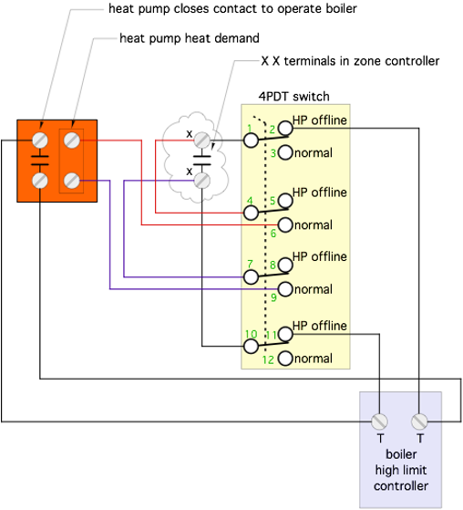 Figure 1. Image courtesy John Siegenthaler
The key component in this circuit is a manually-operated four pole double throw (4PDT) switch. In “normal” mode, this switch allows the isolated heat call contact in a zone controller - usually referred to as the (X X) terminals - to call for heating operation of the heat pump. If the auxiliary heat source needs to operate, another isolated normally open contact within the heat pump closes to enable boiler operation. The schematic in figure 1 assumes that a contact closure across the (T T) terminals in the boiler enables its operation, along with the operation of an associated circulator.
If the heat pump is down for service, the switch is moved to the “HP offline” mode. This mode completely isolates the (X X) contact in the zone controller from the heat pump. Whenever the zone controller closes its (X X) contact, the boiler is called to operate.
Handling DHW Calls
Many systems with an air-to-water heat pump and an auxiliary boiler are configured to provide domestic water heating as well as space heating.
This is where things get more complicated because of variations in how the heat pump and the boiler normally provide heat to an indirect water heater.
Many air-to-water heat pumps now available in North America had their origins in Asian or European markets. These heat pumps often have an internal circulator that’s used in both space heating and domestic water heating modes. They also use a 3-way motorized valve to divert hot water leaving the heat pump to either space heating or the coil of an indirect water heater. Many of these heat pumps also use a temperature sensor inserted into a well in the water heater to determine when domestic water needs heating. Some heat pumps use a 240VAC output to operate the diverter valve while others use a 24 VAC output.
If the heat pump is offline for service, so is the logic to operate the 3-way motorized diverter valve between space heating and domestic water heating modes. One option that keeps the boiler available for space heating and domestic water heating is to “take over” control of the 3-way motorized valve.
The necessary wiring for this depends on how the boiler handles domestic water heating. For example, some mod/con boilers use a temperature sensor inserted into a well in the indirect tank to determine when heat input to the tank is needed. Others wait for a contact closure input that would come from an external setpoint controller that monitors the temperature of the indirect water heater. That setpoint controller could be powered by 120 VAC, 24 VAC, or require no external power if it’s an electro-mechanical aquastat.
The schematic in figure 2 shows how a single 4PDT switch - the same types as shown in figure 1, is used to take over operation of a 24 VAC 3-way diverter valve if the heat pump is not operating, and the boiler is needed for domestic water heating.
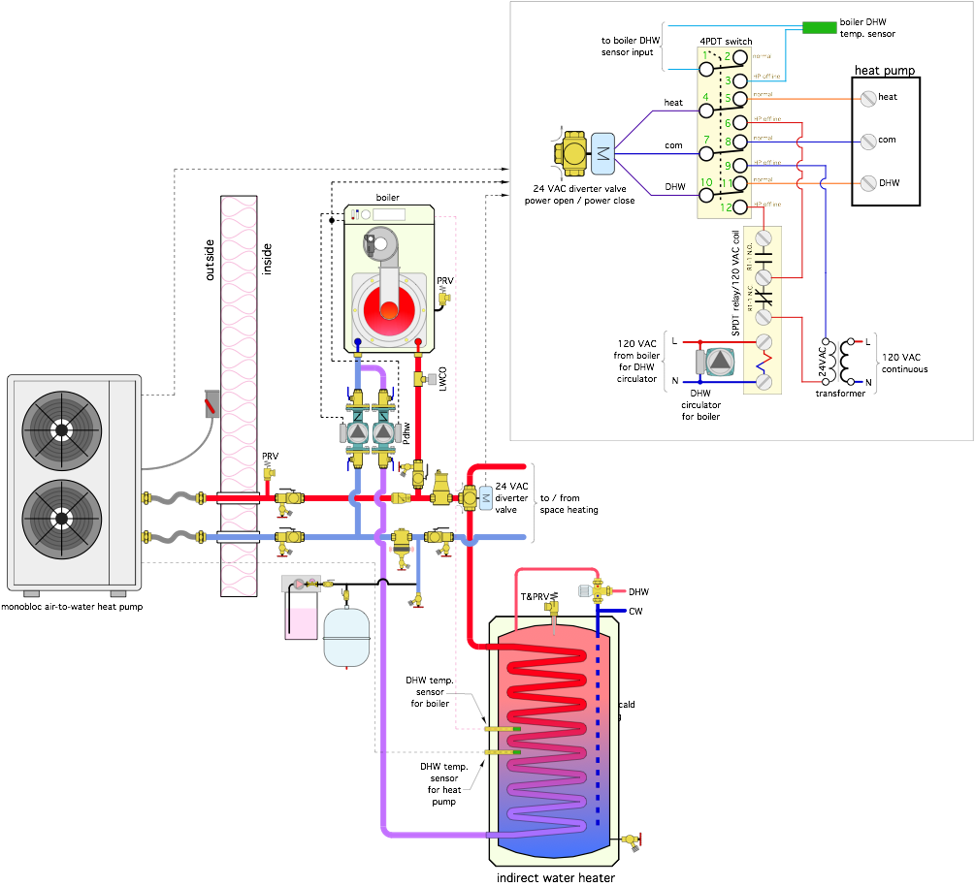 Figure 2. Image courtesy John Siegenthaler
The 4PDT manually-operated switch has two modes: “normal” and “HP offline.” In normal mode, the heat pump supplies the 24VAC outputs needed to operate the diverter valve.
In normal mode, the circuit for the boiler’s DHW temperature sensor is open, so that sensor has no communication with the boiler. If the boiler throws an error code for an open DHW sensor circuit, or if a call for boiler DHW operation uses a contact closure rather than a sensor, some other way of disabling boiler DHW operation during normal mode and based on an open circuit through the 4th pole of the 4PDT switch can be used.
The schematic in figure 2 assumes that the actuator fitted to the 3-way diverter valve is “power open / power closed.” This means that 24 VAC needs to be supplied to the valve’s actuator when:
- The valve needs to stop the flow to the space heating, and supply flow to the indirect tank.
- The valve needs to stop the flow to the indirect tank, and allow flow to space heating.
When the 4PDT switch in figure is set to “HP offline” mode, 24 VAC is sent to the diverter valve to hold it in the space heating mode. When the boiler operates for domestic water heating it supplies 120 VAC to the DHW circulator, as well as the coil of a single pole double throw (SPDT) relay (R1). When this happens the normally open relay contact closes to supply 24VAC to the diverter valve causing it to rotate to the DHW position.
They’re Not All the Same
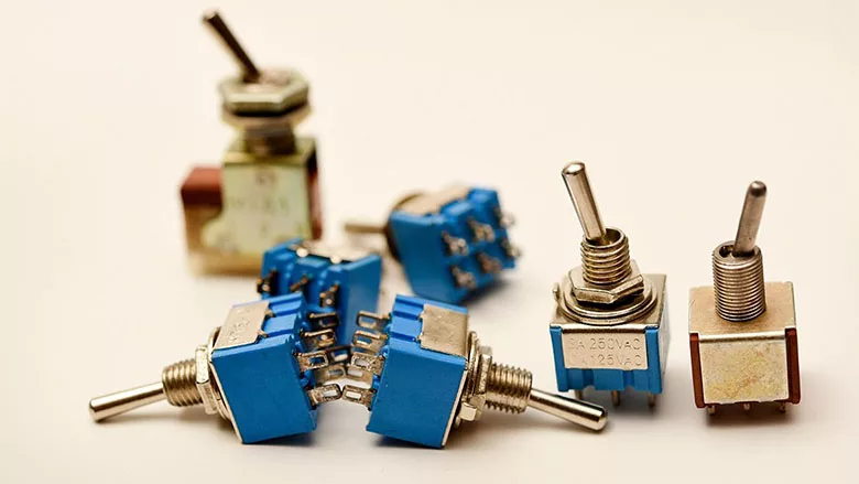
Figure 3 shows an example of an industrial grade 4PDT switch.
 Image courtesy of Cricklewood Electronics.
This switch has 12 terminals. Some switches like this have numbers for each terminal that are molded into the switch body. You may have to squint your eyes to see them. For switches that don’t have numbers, you can assign your own numbers and put them on the schematic symbol of the switch, as shown in figures 1 and 2.
There are variations of 4PDT switches: Some have a “center off” position. Some have a spring that always returns the lever to the center off position whenever a finger is off the switch. The latter are called “momentary contact” switches. For this application, you don’t want either of these variants. You want a simple 2-position switch with no center off or momentary setting. Be sure you check the specs for the switch before ordering it.
If you’re not sure which is the normally open vs. normal closed contacts, just set a multimeter to “continuity” mode, put one lead of the meter on one of the center terminals and the other on one of the outer terminals adjacent to that center terminal. The normally-closed terminal will be the one that makes the multimeter chirp to indicate continuity.
I’ve found that the best was to connect wiring to a 4PDT switch is to make 12 “pigtails” about 10 inches long, crimp a spade terminal to one end of each pigtail, and attach all of them to the switch. Slide a short length of heat shrink tubing over all the switch terminals after the pigtails are attached. Apply heat to shrink the heat shrink tubing. Put a number label near the other end of each pigtail that corresponds to the terminal numbers on the switch body, and on your schematic. Do all of this before mounting the switch in any type of cabinet or faceplate. Finally, mount the switch and connect the pigtails to the remaining wiring using wire nuts or crimp connectors.
Several Possible Combinations
There are several variations on the wiring depending on the specifics of the heat pump and the auxiliary boiler. There are also variations in the actuators used to operate a 3-way diverter valve. Some are power open / power close. Some are power open / spring close.
To determine the correct wiring, remember that the valve actuator has to be controlled by the heat pump or the auxiliary boiler, but only one at a time. This implies that the valve actuator wiring will connect to the “common” terminals on the double throw switch. Also, set up your wiring so that there’s no possibility of inadvertent “cross communication” between circuits in the heat pump and those in the boiler.
insert photo
If you use the circuitry described above, be sure to leave schematics along with an explanation of the circuitry with the system so that a future technician can understand the purpose of the circuitry. Also, make sure you walk the owner through how the switches are to be used, when to move them from normal to heat pump offline settings, and when to reset them to normal.
Leave Instructions
4PDT switches are not very common in most site-wiring associated with HVAC systems. A future service technician may have no idea what such a switch is for. If you use them as described above be sure to:
- Create a schematic like that shown in figures 1 and 2, including numbers on the switch terminals and corresponding number tags on all wiring attached to the switch.
- Create a detailed description of what the switch is for and how it is to be used.
- Leave the schematic and the description with other product manuals for the system, or laminate the schematic and description and post it adjacent to the switch.
- Explain the operation of the switch to the building owner.
- Tell the owner to turn off the power supply to the heat pump if the switch is to be set to “HP fail” mode.
- Tell the owner that the switch must be returned to the “normal” setting after the heat pump is put back online from servicing.
Reasonable & Prudent
When properly matched to loads and balance of system hardware, air-to-water heat pumps are as reliable as other HVAC source equipment. Like other state-of-the-art HVAC source equipment, and many other major home appliances, these heat pumps have lots of sensors and microprocessor-based controls. It is reasonable and prudent to expect that some maintenance will be required over their service lives. When a boiler is present in the system, it’s also reasonable and prudent to expect that it can be easily selected as the sole heat source for the system while the heat pump is down for service. The simple switching arrangement described above makes this possible with minimal added cost or complexity.
Looking for a reprint of this article?
From high-res PDFs to custom plaques, order your copy today!


.jpg")

