The Glitch & The Fix: November 2025
Overlooped: Boiler swap gone wrong

An owner, who has never been satisfied with the performance of his heating system, decides that the boiler must be the root cause of all the performance issues. Not wanting to spend any more than necessary, he makes several calls looking for the lowest boiler replacement price. One company, figuring the inquiry is just a swap out, quotes the job over the phone, sight unseen. When they arrive to do the work, they find the system shown in figure 1.
FIGURE 1
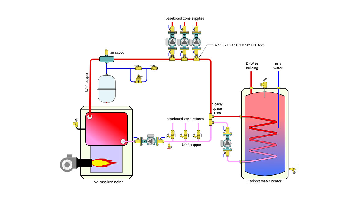
Image courtesy of John Siegenthaler
The installer manages to swap out the boiler before lunch, gets paid by the owner, and heads to the next job. After a few days, the owner complains that the new boiler didn’t correct any of the problems. The installer, faced with involvement in the project, regrets that they didn’t take a closer look before quoting the boiler swap out.
Imagine you were that installer. Take a close look at figure 1 and come up with some things that probably should have been done along with the boiler changeout.
The glitch
The system in figure 1 is one of the “undefined piping aberrations,” where the original installer decided to blend a touch of primary/secondary piping along with standard zone circulator piping. Here’s a list of the problems.
- The system in figure 1 is not a primary/secondary (P/S) system. True, it has a piping loop that starts and ends at the boiler. It even has a pair of closely spaced tees that connect to the indirect water heater. Where the P/S concept breaks down is the grouping of the zone supplies in an attempt to get the same supply water temperature to each zone - like what’s commonly done with a standard “header” system. Likewise, the zone returns are grouped together, just like they would be with a header system. Doing this doesn’t work if you’re trying to create a (P/S) system. Anytime the total flow rate of the active zone circulators exceeds the flow rate in the loop, there will be flow reversal that draws some of the water returning from the zones into the supply side of the zones.
- Even if this were a (P/S) system, why put the indirect tank out at the end of the loop? If the indirect tank is not controlled as the priority load and any of the space heating zones are operating, the heat exchanger coil in the indirect tank is going to receive water that could be substantially cooler than the water leaving the boiler. If the indirect was a priority load, why put it out at the end of the loop, which requires more piping to be heated during warm weather to transfer heat from the boiler to the tank?
Other incorrect or missing details include:
- No way to isolate the indirect tank form the remainder of the system, or conveniently drain its coil if ever necessary.
- No way to isolate the expansion tank from the remainder of the system if it ever has to be replaced.
- No backflow preventer on the make-up water assembly.
- Assuming that this was a (P/S) system, the “primary pump,” would be pumping toward rather than away from the point where the expansion tank connects to the system.
- There should be a minimum of 10 dimeters of straight pipe leading into any circulator. The C x C x FPT tees might seem tempting, since a close nipple could make the connection between the circulator isolation flange and the tee, but such an arrangement will create turbulence at the inlet of the circulator leading to noisy operation and possibly even cavitation.
- Older systems with cast iron boilers are likely to contain iron oxide particles (e.g., magnetite). If left in the system, the magnetite will eventually accumulate in the new boiler reducing its heat transfer efficiency, or worse - foul out future replacement circulators with ECM motors. ECM circulators will be mandated by federal law starting in 2028.
- Whoever used 3/4” piping to feed 4 zones with individual circulators should find another line of work. To provide good hydraulic separation between the circulators, the header should be sized for a maximum flow velocity of 2 feet per second.
- There’s no ASSE 1017 thermostatic mixing valve at hot water outlet of the water heater. All that’s separating this situation from a scalding burn and subsequent litigation is the hope that everyone in the house knows enough to blend hot and cold water at the fixtures.
- The purging valves on the zone returns are installed backwards.
The fix
Figure 2 shows a better water to reconfigure the piping.
FIGURE 2
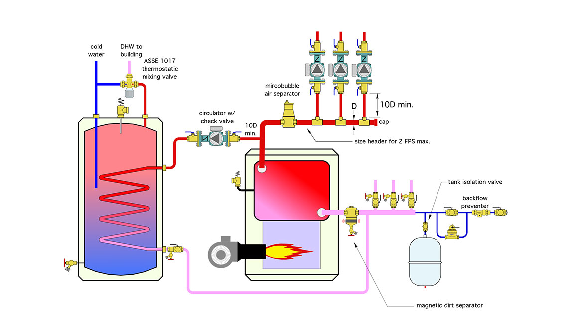
Image courtesy of John Siegenthaler
- The loop is gone, and the system has been converted to generously size supply and return headers.
- Piping to the indirect tank is as close as possible to minimize piping heat loss.
- A magnetic dirt separator has been installed, along with a microbubble air separator.
- Zone purging valves are correctly oriented.
- A minimum of 10 pipe diameters of straight pipe has been installed leading into each circulator.
- An ASSE 1017 thermostatic mixing valve has been installed at the DHW output of the indirect water heater.
- The make-up water system now includes a backflow preventer.
Looking for a reprint of this article?
From high-res PDFs to custom plaques, order your copy today!


