The Glitch & The Fix: September 2025
Right & wrong: Examining common design pitfalls, and how to optimize piping strategies
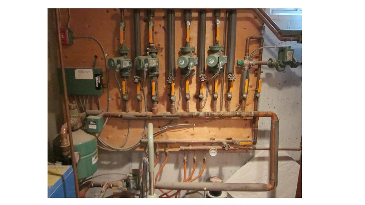
Figure 1
The installation in figure 1 uses a propane-fired cast-iron boiler to provide heat to four zones of plateless staple-up underfloor heating, and one zone of slab heating.
The four zones of plateless staple-up underfloor heating are each configured as secondary circuits supplied from a common primary loop. The zone supplying slab heating is equipped with a 3-way thermostatic mixing valve. You can see that zone on the far right of the primary loop.
The system “sorta works” as is. Look it over and see if you can identify some changes that would improve the layout.
The “issues”: The five secondary circuits served by a series primary loop is a legitimate approach IF the designer accounts for the temperature drop along the primary loop from one secondary circuit to the next. If that hasn’t been done the fourth secondary circuit could have a supply temperature much lower than the first. That temperature difference would depend on which upstream circuits are operating.
The primary loop circulator, seen near the bottom of the photo, is mounted with a vertical motor shaft (not a good idea), and it’s pumping toward (rather than away from) the location where the expansion tank taps into the loop (e.g., at the bottom of the air separator).
You can see the circulator for the slab heating zone is also mounted with its motor shaft vertical (still not a good idea). Its inlet is also close to the outlet of the mixing valve. That valve probably has a Cv in the range of 2.5-3.5 making for a relatively high head loss and turbulence - not good effects near the inlet of any circulator. Fortunately, it looks like that zone only serves three floor heating circuits. Assuming a nominal 1 gpm per circuit, the low Cv of the mixing valve is probably acceptable.
The designer of the system shown in figure 1 likely assumed that the water temperature returning from the plateless staple-up floor circuits would be high enough to prevent sustained flue gas condensation within the boiler. Maybe… but definitely not guaranteed.
The designer is also ignoring the low operating temperature and high thermal mass of the heat slab subsystem. If that slab were the only zone operating, the water temperature entering the boiler would be well below the dewpoint temperature of the flue gases. Sustained condensation of those flue gases is virtually guaranteed. Even if some of the higher temperature zones were operating simultaneously with the floor circuits, there’s no guarantee that the blended boiler inlet temperature would be high enough to prevent flue gas condensation.
Another detail, one that’s commonly overlooked, is the need for a check valve - other than the one that might or might not be in the circulator - to prevent the possibility of reverse flow through the mixing valve when its internal spool is partially open to both the hot and outlet ports. Without this valve, there can be flow from the return side of the zone, back through the mixing valve, and back through an inactive zone circuit. This possible flow path is illustrated in figure 2.
FIGURE 2
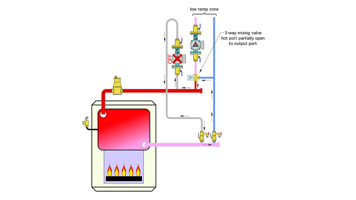
Image courtesy of John Siegenthaler
How much reverse flow occurs depends on the flow resistance through the heat source and header piping compared to that through the mixing valve and inactive zone circuit. The latter will tend to have higher flow resistance and thus minimize this effect. Still, the goal is to have zero flow, forward or reverse, through any inactive zone circuit.
An alternate design: Figure 3 shows a piping technique that eliminates the series primary loop, its associated temperature drop issues and the primary loop circulator.
FIGURE 3
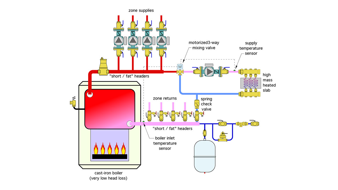
Image courtesy of John Siegenthaler
This design capitalizes on the fact that cast-iron boilers have very low head loss. When such a boiler is fitted with “short/fat” headers (e.g., sized for a maximum flow velocity of 2 feet / second), hydraulic separation between the circulators is achieved. There’s no need for a primary loop or closely spaced tees.
Each of the four higher temperature zones gets the same water supply temperature, and that same temperature is also available at the hot port of the 3-way mixing valve.
The low Cv thermostatic mixing valve seen in figure 1 has been replaced by a 3-way motorized mixing valve. The controller for that valve accepts input from the boiler inlet temperature sensor and limits hot water flow through the valve when necessary to keep the boiler inlet temperature above the dewpoint of the flue gases.
A spring check valve has been installed upstream of the purging valve for the low temperature zone to prevent any possibly of reverse flow.
You might be wondering why the expansion tank and make-up water assembly is not tapped into the bottom of the air separator. It could be, but putting it on the end of the return header is also fine. The very low head loss though the return header and boiler effectively - from the standpoint of pressure drop - puts the expansion tank near the supply header and thus near the inlet of the circulators. The placement shown also tends to keep the shell of the expansion tank cooler, and is ideal from the standpoint of adding water to the system and clearing out air through the purging valves just above the return header.
But what if…?
Let’s assume that the plateless staple-up floor heating eventually gets an “upgrade” to a properly plated and insulated system (likely due to unfulfilled comfort expectations from the initial installation). Or, maybe someone decides to add outdoor reset control to the boiler. Both of these changes could bring down the system’s operating temperature to the point where even the “higher temperature” zones are producing return water temperatures below the dewpoint of the boiler flue gases - resulting in sustained flue gas condensation.
The solution is to install a “thermal clutch” between the boiler and the balance of the distribution system. There are several hardware configurations that can be used. One of the simplest is a high flow capacity thermostatic anti-condensation valve, installed along with an additional circulator, as shown in figure 4.
FIGURE 4
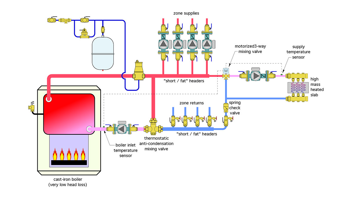
Image courtesy of John Siegenthaler
The system shown in figure 1 is not a “disaster.” It’s also far from an optimal design. It uses more hardware than necessary and arranges that hardware in ways that create some undesirable effects - such as the temperature drop along the series primary loop. The alternate designs shown in figure 3 and 4 are simpler, potentially less expensive, and eliminate all the issues of the system shown in figure 1.
Looking for a reprint of this article?
From high-res PDFs to custom plaques, order your copy today!


