When and how to use reverse return piping
In many hydronic systems, there’s a need to divide the overall system flow into equal streams that pass through several identical components.
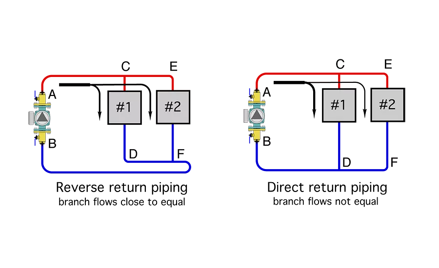
Figure 1 shows a simple representation of reverse return piping through two identical components, each in its own branch piping. Graphics credit: John Siegenthaler
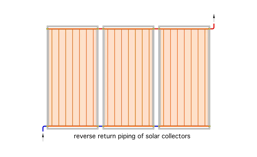
An example would be multiple solar thermal collectors, as shown in Figure 2. Graphics credit: John Siegenthaler
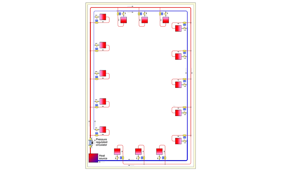
Figure 3 shows an example of a reverse return distribution system that meets these requirements. Graphics credit: John Siegenthaler

Reverse return piping doesn’t make sense when the distribution system “dead ends,” as shown in Figure 4. Graphics credit: John Siegenthaler
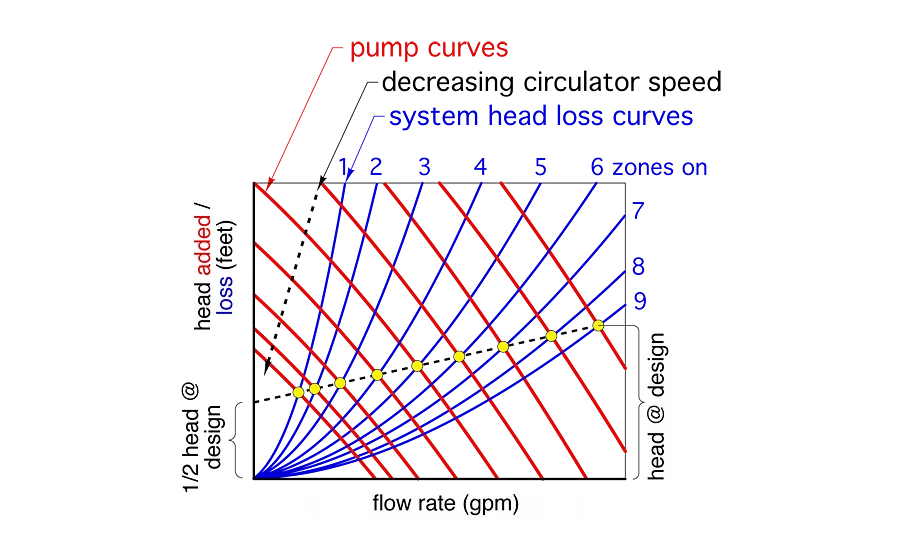
Figure 5 shows how proportional differential pressure mode operates on most currently available electronically commutated motor (ECM) circulators. Graphics credit: John Siegenthaler

Another situation in which reverse return piping is not needed is when multiple boilers are closely grouped together and piped to a common device such as a hydraulic separator, as illustrated in Figure 6. Graphics credit: John Siegenthaler

Another situation where reverse return is acceptable but not required is a typical manifold station for radiant panel heating circuits, as shown in Figure 7. Graphics credit: John Siegenthaler
In many hydronic systems, there’s a need to divide the overall system flow into equal streams that pass through several identical components. The physics necessary for this are simple: If the flow resistance of each piping path from a common source point to a common return point is the same, the flow will divide equally. Reverse return piping was developed to help achieve this goal.
Figure 1 shows a simple representation of reverse return piping through two identical components, each in its own branch piping. It also shows a direct return piping layout for comparison. The reverse return arrangement has the potential to create approximately equal flow resistance through each branch and produce flows that are closer to equal. The branch flows in the direct return system will not be equal. A higher percentage of the total flow will pass through branch No. 1.
However, just because two or more branches are piped in reverse return does not imply that each branch will operate at the same flow rate. Anything that creates a difference in the flow resistance of the supply or return piping between points where the branches connect will affect branch flow proportions, as would a different type or size of heat emitters in any of the crossovers. A difference in the crossover piping itself (length, type, or size) would also change the flow resistance of that branch relative to the others and thus affect flow proportions. Balancing valves should still be installed in each branch of a reverse return system to “fine tune” the flow rates to their calculated design load values.
When reverse return makes sense
Reverse return piping subassemblies make sense when two or more identical devices require equal flow proportions and have a common supply. An example would be multiple solar thermal collectors, as shown in Figure 2.
Reverse return distribution systems that serve multiple heat emitters make sense when all of the following conditions are met:
-
The loads are being supplied from a common circulator;
-
The loads served require the same supply temperature;
-
The loads served are widely dispersed around the building; and
-
The distribution piping can make a complete loop around the inside of the building, starting and ending in the mechanical room.
Figure 3 shows an example of a reverse return distribution system that meets these requirements.
Notice that the supply pipe size decreases as the circuit moves away from the heat source while the return pipe size increases. Pipe size changes are made to keep flow velocity or head loss along the main approximately equal. For pipe sizes of 2 inches and smaller, flow velocity should generally not exceed 4 feet per second. For larger pipes, sizes should be selected to maintain the head loss along the pipe in the range of 4 feet of head loss per 100 feet of pipe.
In systems with relatively short supply and return mains, the designer may elect to use the same pipe size for all mains. This decreases system head loss, which may, in turn, reduce circulator size. However, it also increases piping cost.
Not here
Reverse return piping doesn’t make sense when the distribution system “dead ends,” as shown in Figure 4.
Such an arrangement requires a “third pipe” sized to carry the full system flow from the dead end back to the mechanical room. While this arrangement still provides approximately equal supply water temperatures, and is closer to self-balancing relative to a direct return system, the third pipe running the entire length of the system adds substantial cost.
Controlling ∆P
Although reverse return systems are closer to self-balancing than direct return systems, they still cause a fixed-speed circulator to experience changes in differential pressure due to changes in flow as the valves controlling flow through the branches open, close, or modulate. If uncorrected, these changes in differential pressure can cause flow velocities in active branches to increase as valves on other branches close or modulate to lower flow. This can lead to flow noise, weepage through valves that are supposed to be closed, and erosion of copper tubing.
The best solution is use of a variable-speed circulator operating in proportional differential control mode. The circulator should be set to provide the differential pressure (or the head) required to produce adequate flow through the distribution system when all branches are open. As the branch valves close, the circulator automatically detects “attempted” increases in differential pressure and reduces speed to compensate. The goal of the circulator’s internal controller is to adjust differential pressure so that the flow through each active branch remains as stable as possible regardless of what other branches are operating.
Figure 5 shows how proportional differential pressure mode operates on most currently available electronically commutated motor (ECM) circulators. The circulator is set to the differential pressure required at design load conditions (when all branches are open). The circulator’s controller then adjusts speed so that the operating points (where the pump curve and system head loss curves cross) track along a sloping line that ends at 50% of the design load condition at zero flow.
Another situation in which reverse return piping is not needed is when multiple boilers are closely grouped together and piped to a common device such as a hydraulic separator, as illustrated in Figure 6.
The key concept here is to keep the headers as short as possible and size them for very low pressure drop. A suggested sizing criterion is to select the header piping for a flow velocity of about 2 feet per second when carrying the total flow produced by all boiler circulators running simultaneously.
Because the pressure drop along the boiler headers is so low in comparison to the flow resistance through the boiler heat exchanger, there is minimal difference in the flow rate through each boiler path, regardless which boiler circulators are operational. Any slight variation is of no consequence since all flows will be combined at the hydraulic separator.
Another situation where reverse return is acceptable but not required is a typical manifold station for radiant panel heating circuits, as shown in Figure 7.
Again, because the pressure drop along the short manifold is extremely low in comparison to the pressure drop along a typical radiant panel circuit, the use of reverse return piping will have virtually no effect on individual circuit flows. The larger the bore of the manifold relative to the number of circuits it serves, the less effect reverse return piping has. Keep in mind that the floor circuits may not all be the same length and don’t necessarily need equal flow rates.
Reverse return piping is an important concept in hydronics technology. If you design hydronic systems, you should know when to apply it and when it’s not necessary.
This article was originally titled “Reversing course” in the November 2016 print edition of Plumbing & Mechanical.
Looking for a reprint of this article?
From high-res PDFs to custom plaques, order your copy today!


