The Glitch & The Fix: Januar 2025
A hydro-split air-to-water heat pump system that ‘sorta’ works

Image courtesy of John Siegenthaler
The Glitch
An installer is asked to provide a hydro-split air-to-water heat pump to supply several zones of space heating and an indirect domestic water heater. No cooling is required for the project. The hydro-split heat pump consists of an outdoor unit and an indoor unit connected by piping carrying an antifreeze solution. The heat pump is turned on whenever one or more zone thermostats call for heat. It then modulates to maintain a fixed outlet temperature of 110° F. The heat pump’s internal controller boosts its outlet temperature to 130° F when the indirect water heater calls for heat. During this mode, a 3-way diverter valve directs flow from the heat pump through the coil heat exchanger with the indirect water heater.
Although the system operates, the building occupants notice that recovery from a night setback takes a long time. They’ve also noticed that domestic hot water delivery falls off quickly during high-demand periods. The system is piped as shown in Figure 1. Can you think of some changes that would improve the system’s performance?
FIGURE 1

Image courtesy of John Siegenthaler
The Fixes
Although the system "sorta works," there are several details that could improve it.
The presence of a hydraulic separator and a buffer tank is an indication that more hardware than necessary is used. A hydraulic separator or a properly configured buffer tank can provide hydraulic separation between the circulators. Very seldom are both needed.
The reconfiguration shown in Figure 2 uses a buffer tank, piped in a "3-pipe" configuration, to eliminate the need for a hydraulic separator.
FIGURE 2
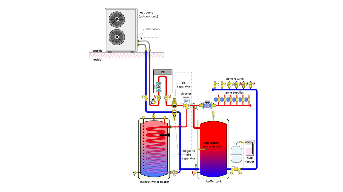
Image courtesy of John Siegenthaler
Notice that flow from the heat pump’s indoor unit (IDU) does not have to pass through the buffer tank on its way to the zone circuits. This helps reduce or even eliminate the time delay for delivering heat to the zone circuits that would otherwise occur by forcing all flow through the buffer tank, which may have cooled over several hours during a setback period.
If the flow rate from the heat pump happens to be equal to the total flow of the zone circuits, it passes straight through the diverter valve, through the variable-speed pressure-regulated circulator, and on to the active zones.
If the flow rate from the heat pump is greater than the flow rate through the zone circuits, the difference between these flow rates passes into the upper horizontal inlet of the buffer tank. The direction of that inlet piping — horizontal — is important, it reduces mixing currents inside the tank, which helps preserve beneficial temperature stratification.
If the flow rate from the heat pump is less than the total flow of the zone circuits, the difference in the two flow rates flows out of the upper connection on the buffer tank.
If the heat pump is off, and there’s flow in the zone circuits, all of that flow passes vertically up through the buffer tank. This allows the buffer tank to provide heat to the space heating zones at the same time the heat pump is servicing the indirect water heater.
What’s in common?
So how does this buffer tank provide hydraulic separation between the heat pump circulator and the distribution circulator?
Consider the head loss of the piping between points A and B in Figure 2. Most of the piping path length is through the buffer tank. Even at flow rates of several gallons per minute, the wide diameter of the buffer tank relative to the piping creates insignificant head loss.
The short piping segment from the upper left connection on the buffer tank to point A, should also create minimal head loss.
Collectively, the piping and components between points A and B represent the "common piping" shared by the circuit through the heat pump and the branches of the distribution system. When the head loss of the common piping between any two "overlapping" hydronic circuits is very small, those circuits are hydraulically separated. Each circulator, in effect, only "sees" its own circuit, and, as such, creates insignificant interference with the other circuit. This concept is relatively simple and allows designers to reduce complexity and cost while achieving the desirable characteristic of hydraulic separation.
When buffer tanks are piped this way it’s critical to control the heat pump based on the temperature on the buffer tank - not calls from the zone thermostats. The control logic can be a setpoint temperature with associated differential, or outdoor reset control. The latter is preferred since it keeps the water temperature lower under partial load conditions. This increases the seasonal Coefficient Of Performance (COP) of the heat pump.
With this method of control, the heat pump only "sees" the temperature status of the buffer tank. As such, the heat pump’s sole "responsibility" in space heating mode is to maintain that temperature based on its control settings. The heat pump doesn’t "see" the status of the zone thermostats.
There are two control options for enabling heat pump operation:
- Allow the heat pump to maintain the buffer tank temperature 24/7 based on its controller settings (e.g., setpoint temperature or outdoor reset);
- Allow the heat pump to maintain the buffer tank temperature only when one or more zones are calling for heat;
If you’re using thermostatic radiator valves rather than zone valves, the heat pump needs to maintain the buffer tank temperature 24/7, since radiator valves don’t "call" for heat through an electrical signal, (control method 1). This method would typically be combined with the continuous operation of a distribution circulator that operates on either constant or proportional differential pressure control.
If you’re using zone valves, their end switches can be wired in parallel to call for heat pump operation (control method 2).
Rather than zone circulators, the system shown in Figure 2 uses a single variable-speed pressure-regulated circulator and six zone valves. This reduces installation and operating costs.
Coil constriction
The coils in many indirect water heaters were designed around the assumption of being supplied from boilers at relatively high water temperatures. They don’t necessarily have sufficient surface area to dissipate the full output of the heat pump when operating at coil inlet temperatures of only 130° F. This is likely the reason the occupants run out of domestic hot water during periods of high demand. Furthermore, if the tank has been in service for several years, operating at high coil temperatures, and the domestic water has high total dissolved solids (TDS), there is likely to be scale on the coil, further reducing its heat transfer capacity.
Notice that the heat exchanger coil in the indirect water heater of Figure 2 is much larger than that shown in Figure 1. The larger the coil, and the greater its surface area, the lower the water temperature required to sustain a given rate of heat transfer from the coil into the domestic water. Again, lower water temperatures improve the COP of the heat pump.
Another detail missing in Figure 1 is a pressure relief valve. Any closed-loop hydronic circuit containing a heat source should have a pressure relief valve.
Two combination purging/isolation valves are shown in the piping under the indoor unit. These allow that unit to be isolated and drained if ever necessary for service.
Two pressure-rated flexible hoses have been used to connect the heat pump to the rigid piping. These short hoses help attenuate vibration from the heat pump to the rigid piping, which minimizes the perceptible sound of the heat pump. Modern air-to-water heat pumps with variable-speed compressors are remarkably quiet compared to early-generation products. Still, keeping the overall system as quiet as possible should be the goal of any hydronics professional.
Finally, the system in Figure 2 includes a double port fill/purge valve through which a water/antifreeze solution can be pumped in to fill the system as air is removed. An automatic fluid feeder has also been added to ensure the minor fluid losses over time are replenished and thus system pressure is maintained.
Looking for a reprint of this article?
From high-res PDFs to custom plaques, order your copy today!


