How to design and size PEX pipe the right way
Most plumbers in residential construction know PEX. They have either used it themselves or know other professionals that are using it. That’s because PEX is the piping product used in more new-home construction than copper and CPVC combined.
With larger pipe sizes now available up to 3 inches, the commercial industry is making the switch to PEX due to the installation efficiencies, job-site safety and profitability potential it can provide. With this trend continuing to grow, gaining a better understanding of PEX and learning the best design and installation practices will give professionals an advantage when it comes to future commercial construction projects.
Beginning with design
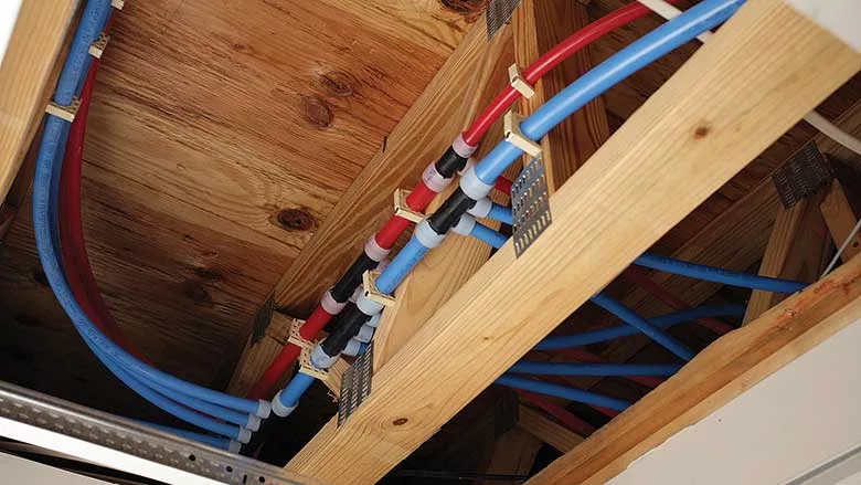
The design benefits of PEX begin with the small-diameter sizes, which are available in long coil lengths up to 1,000 feet. The flexible nature of PEX means the pipe can bend with each change in direction without the need for elbows and added fittings. Fewer fittings in a system offer better flow rates and reduced pressure loss.
Couple the flexibility of PEX with multiport tees, and you now have a Logic design. This layout combines the best attributes of trunk-and-branch and homerun piping systems while improving on both. Using multiport tees in a Logic system reduces the overall number of fittings when compared to a trunk-and-branch system and requires less overall pipe than a homerun system.
The benefit of Logic also extends to system operation. When comparing the “critical path” of pipe from a water heater to a bathtub, delivery times and pressure loss are also the least in a Logic system.
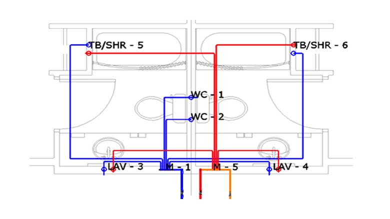
In commercial applications, the Logic design allows for the efficient joining of back-to-back bathroom groups, reducing the overall number of required risers, penetrations and access boxes for valves. For an example of this, refer to Figure 1, which shows a Logic design in a hotel application.
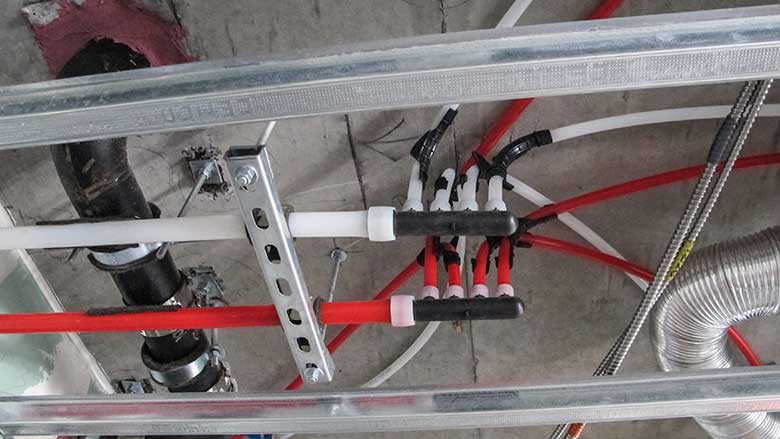
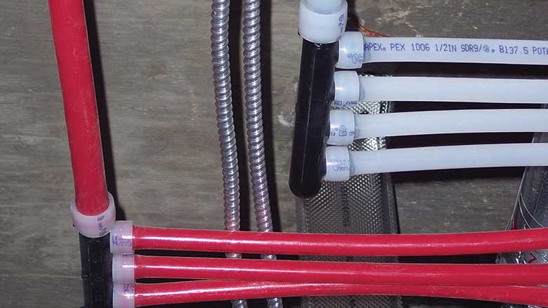
Public fixtures, or those using fast-acting valves or flush valve fixtures, are another ideal application. The elasticity of PEX allows it to absorb 18% to 40% greater surge pressures than metallic piping. It also absorbs significantly more sound decibels than metallic pipes, which can be eight times louder. Refer to Figure 2 for an example of Logic in a public fixture application.
For in-slab applications, PEX also offers substantial benefits. The pipe’s flexibility allows it to avoid obstructions and eliminates the product costs and labor requirements for hangers. While pre-sleeved PEX coils are ideal for in-slab installations, bare PEX is also listed for use in concrete as well as below-grade and water-service applications.
Lastly, for safety purposes, PEX offers a significantly lighter weight compared to metal piping systems. For example, a 300-foot coil of 1/2-inch PEX weighs 18 pounds, whereas the same amount of copper weighs 85.5 pounds. This benefit not only provides greater job-site safety, but it also allows easier transport options and eliminates heavy lifting equipment from the construction site.
Expansion and contraction considerations
All piping systems expand and contract at various rates depending on the temperature differences (or Delta T) of the fluid running through the piping. For PEX, it expands and contracts at a rate of 1.1 inches per 100 feet per 10° F ∆T.
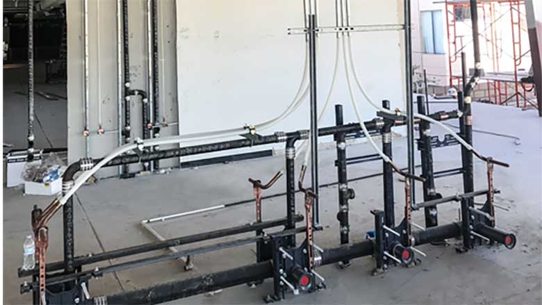
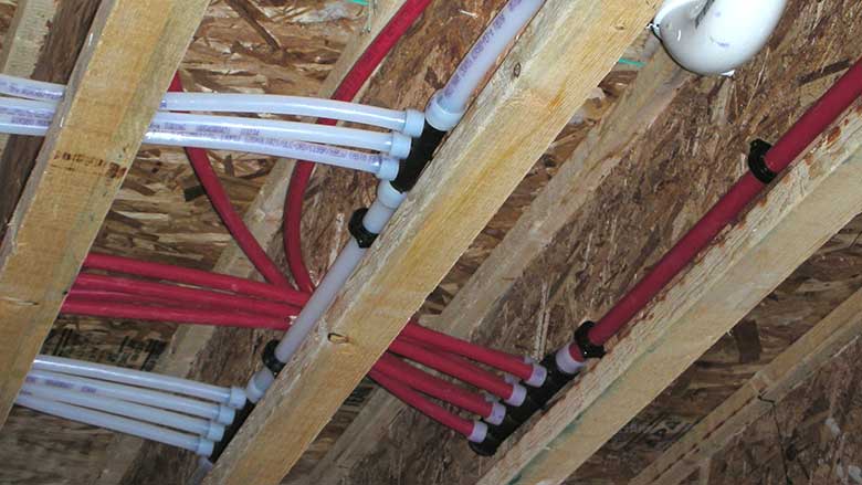
There are steel support channels available that snap onto the pipe and provide continuous support for suspended-piping applications. Using these channels in conjunction with fixed points can help reduce expansion and contraction rates to an acceptable level similar to metal piping systems.
When using these support channels, be sure to use a minimum 300-pound, tensile-rated strap to secure the support to the pipe. The strap must also meet the minimum temperature requirements of the system and be able to withstand the project area’s UV levels.
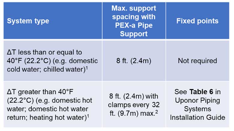
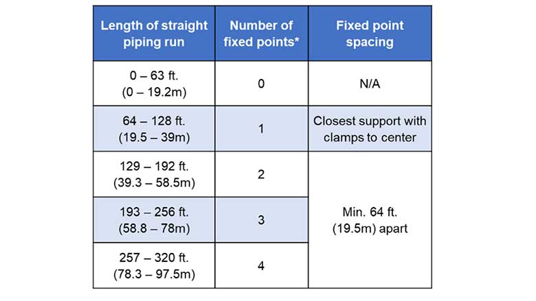
Support spacing and fixed-point placement is dependent on both the system operating temperature and the ambient temperature of the space, as well as the length of the piping run. In general, the higher the operating temperature and longer the run, the more fixed points needed to help maintain system integrity and aesthetics. For guidance, refer to Figures 3 and 4 for support and fixed-point recommendations.
Because PEX pipe is manufactured with a copper tube size (CTS) outside diameter and an SDR of 9, it allows designers and installers to use the same hangers, supports and insulation as copper piping systems. For risers, use CTS riser clamps on the base of each floor to control for expansion and contraction. In hot-water applications, add an extra clamp at the top of every other floor. For cold water, add one at the top of every fourth floor. Additionally, most code bodies also require mid-story guides to guide the pipe and maintain proper direction. For PEX, use an iron pipe size (IPS) support for mid-story guides.
Sizing PEX properly
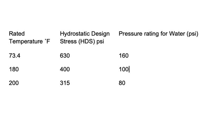
PEX pipe is manufactured using three different methods: PEX-a, PEX-b and PEX-c. The classification calls out the varying degrees of crosslinking in the pipe. PEX-a pipe, which features the highest degree of crosslinking for the greatest flexibility and durability, will burst in the 800 psi (pounds per square inch) range, which is nearly double the minimum requirement of ASTM F876 Standard Specification for Crosslinked Polyethylene (PEX) Tubing. Figure 5 shows the temperature and pressure ratings for SDR 9 PEX.
For design purposes, it is important to understand the various types of fitting connections available for PEX pipe:
- ASTM F1807 Standard Specification for Metal Insert Fittings Utilizing a Copper Crimp Ring for SDR9 Cross-linked Polyethylene (PEX) Tubing and SDR9 Polyethylene of Raised Temperature (PE-RT) Tubing;
- ASTM F2159 Standard Specification for Plastic Insert Fittings Utilizing a Copper Crimp Ring for SDR9 Cross-linked Polyethylene (PEX) Tubing and SDR9 Polyethylene of Raised Temperature (PE-RT) Tubing;
- ASTM F2098 Standard Specification for Stainless Steel Clamps for Securing SDR9 Cross-linked Polyethylene (PEX) Tubing to Metal Insert and Plastic Insert Fittings;
- ASTM F877 Standard Specification for Crosslinked Polyethylene (PEX) Plastic Hot- and Cold-Water Distribution Systems; and
- ASTM F1960 Standard Specification for Cold Expansion Fittings with PEX Reinforcing Rings for Use with Cross-linked Polyethylene (PEX) Tubing.
When specifying fittings, it is important to design with the same system intended to be used in the application. If specifying a PEX system with ASTM F1960 fittings, but the contractor installs any of the alternatives, it will significantly impact the system velocity and performance.
Most residential and commercial professionals prefer ASTM F1960 fittings because they are easy to learn, provide a reliable connection and can never be dry fit. To make a connection, the installer simply uses an expansion tool to expand the pipe and expansion ring before inserting the fitting. As the ring and pipe shrink back down to their original size, it creates a strong, durable connection that holds tight.
This fitting system also provides greater system flow and performance. For example, a 1-inch F1960 engineered polymer (EP) fitting has a 67% greater flow rate, at 8 feet per second, than an F2159 plastic fitting and 22% greater flow rate than an F1807 brass fitting.
Speaking of flow, when it comes to compiling friction loss data, using the Darcy-Weisbach formula is much more accurate and does not employ correction factors for different water temperatures like Hazen Williams. Friction loss data compiled by Uponor utilizes this method and has been backed by empirical NSF laboratory test data, making it an excellent free resource for maximizing system sizing and efficiency.
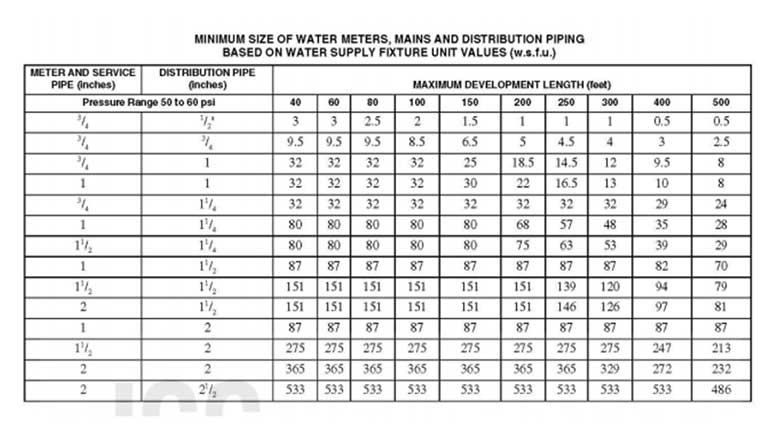
There are three ways to size a PEX piping system with ASTM F1960 fittings. The first is to use model code fixture unit tables (see Figure 6). Of course, this method applies only to systems whose scopes fall within the table.
IAPMO and ICC have confirmed compliance with using fixture unit tables to determine pipe size for systems using the ASTM F1960 fitting system.
A second method involves residual pressure, which determines the critical path by the most remote or demanding fixture. Utilize friction-loss data and calculate system loss from the fixture to the source, ensuring that a PEX replacement would provide sufficient pressure. The result may require up-sizing high-loss cold-water pipe segments. However, it may be possible to downsize some hot-water pipe segments due to the difference between the design velocities of copper and PEX.
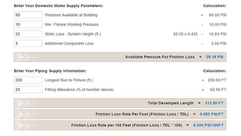
Finally, a third method of sizing pipe is the uniform friction loss method. This method uses the physical layout of the structure to determine pipe sizes. This method requires information such as available static pressure, building height, and distance to the farthest fixture to complete the calculation. After compiling the data, the designer can determine a pressure loss per 100-foot (or per foot) number by dividing the total developed length by the pressure available for loss (see Figure 7).
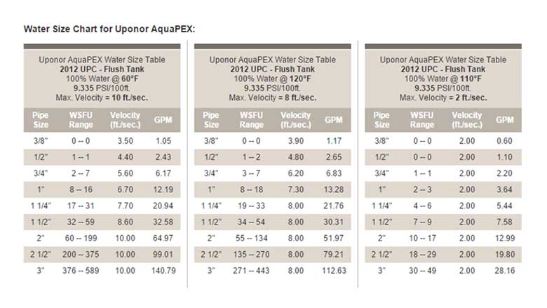
This number is then used to create water supply fixture unit (WSFU) tables for each pipe material and water temperature (see Figure 8).
For quick and accurate PEX pipe sizing, some manufacturers even offer a free pipe-sizing calculator. For example, Uponor has an online calculator at https://tools.uponorpro.com/calculator/ that provides calculations for plumbing, hydronic piping, and radiant systems in addition to pipe heat loss data. There are also tables available in digital format and in design manuals which are easy to access from the company website.
In conclusion, there are many resources and tools available to help piping design and installation professionals create and install high-performing systems with PEX. Leveraging PEX design expertise and following best installation practices will help improve system performance and reliability to maximize high-performing buildings and move the commercial construction industry forward.
Looking for a reprint of this article?
From high-res PDFs to custom plaques, order your copy today!


