The Glitch & The Fix: Mixed results


The Glitch:
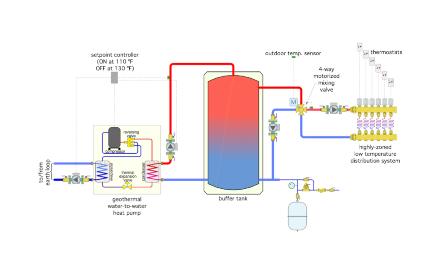
An installer is asked to connect a single speed geothermal water-to-water heat pump to a highly-zoned low temperature hydronic distribution system. The installer realizes that when a single speed heat pump is connected to such a distribution system, it is essential to use a buffer tank, so one is installed, as shown in Figure 1.
The system uses a temperature setpoint controller to operate the heat pump so the buffer tank is maintained between 110° F and 130° F. It also uses a 4-way motorized mixing valve to control the supply water temperature to the distribution system based on outdoor reset control. At design load, the distribution system requires 125°. The heat pump is enabled to operate whenever any of the zone thermostats call for heat. The system has a 2 gallon expansion tank.
Can you identify several details that are wrong, and propose a better design?
The Fix:
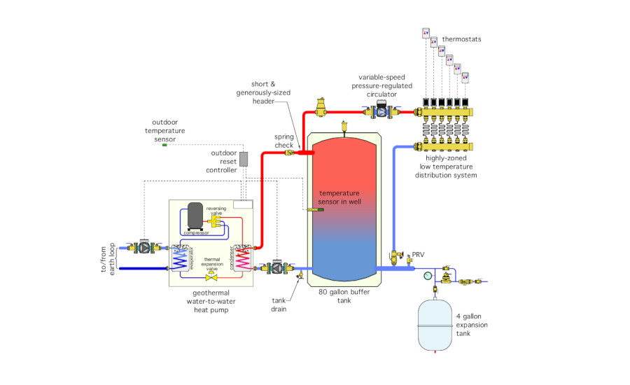
The key to good performance with water-to-water heat pumps is keeping the load water temperature as low as possible. It makes no sense to maintain the buffer tank at a higher temperature than necessary, and then mix down to achieve the required supply water temperature to the heat emitters. The 4-way mixing valve, which is specifically intended to interface a conventional boiler to a low temperature load is completely unnecessary, and has been eliminated in Figure 2.
Other Changes include:
- Set up the buffer tank in a 3-pipe configuration to allow direct-to-load heat transfer between the heat pump and distribution system when both are operating at the same time. Also avoid buffer tanks configurations where flow enters vertically at the top of the tank.
- Install a check valve between the heat pump and buffer tank to prevent reverse thermosiphoning when the tank is warm and the heat pump is off. Without this valve, which might be integrated into the circulator, warm water will slowly flow backwards through the inactive heat pump and its piping, unnecessarily dissipating heat to the surrounding space.
- Use an outdoor reset controller to turn the heat pump and its associated circulators on and off based on the temperature at a sensor located in a well at the mid-height of the tank. This keeps the water temperature just warm enough to maintain comfort in the building while also allowing the heat pump to operate at the highest possible COP.
- Based on an estimated system volume of 120 gallons, an assumed system height of 10 feet, a maximum water temperature of 120°, the expansion tank needs to have a minimum volume of 4 gallons.
- The original system lacked any means of differential pressure control on the highly zoned distribution system. This has been corrected by using a variable-speed pressure-regulated circulator for the distribution system.
- The original system lacked a central air separation device. This has been added in Figure 2.
- The original system lacked a means of removing air from the top of the buffer tank. A float-type air vent has been added at the top of the tank in Figure 2.
- The original system shows a circulator, on the right side of the tank, pumping toward the point of no pressure change. This circulator is not necessary. Even if it were, it’s not in the correct location relative to the point where the expansion tank connects.
- The sensor for the mixing valve is shown very close to the outlet of that valve. Mixing may not be completed at this point and thus the temperature felt by the sensor may not be the true supply temperature to the heat emitters. Always locate the supply temperature sensor for a mixing valve downstream of the circulator (assuming that the circulator is on the supply side of the heat emitters).
- Notice that the expansion tank is connected to the buffer tank. Thus there will be very little change in the pressure within the buffer tank when these circulators operate. Both circulators in Figure 2 have been located so that they pump away from the buffer tank.
- A drain valve has been added to allow the buffer tank to be emptied if ever necessary.
- A pressure relief valve has been added near the expansion tank connection.
Looking for a reprint of this article?
From high-res PDFs to custom plaques, order your copy today!


.jpg")
