search
cart
facebook instagram twitter linkedin youtube
  • Sign In
  • Create Account
  • Sign Out
  • My Account
  • NEWS
  • PRODUCTS
    • FEATURED PRODUCTS
  • CONTRACTORS
    • BATH & KITCHEN PRO
    • BUSINESS MANAGEMENT
    • HIGH EFFICIENCY HOMES
    • TECHNOLOGY
    • WATER TREATMENT
    • PMC COLUMNS
      • Dave Yates: Contractor’s Corner
      • John Siegenthaler: Hydronics Workshop
      • Kenny Chapman: The Blue Collar Coach
      • Matt Michel: Service Plumbing Pros
      • Scott Secor: Heating Perceptions
  • ENGINEERS
    • CONTINUING EDUCATION
    • DECARBONIZATION | ELECTRIFICATION
    • FIRE PROTECTION
    • GEOTHERMAL | SOLAR THERMAL
    • PIPING | PLUMBING | PVF
    • PME COLUMNS
      • Christoph Lohr: Strategic Plumbing Insights
      • David Dexter: Plumbing Talking Points
      • James Dipping: Engineer Viewpoints
      • John Seigenthaler: Renewable Heating Design
      • Lowell Manalo: Plumbing Essentials
      • Misty Guard: Guard on Compliance
  • RADIANT & HYDRONICS
    • RADIANT COMFORT REPORT
    • THE GLITCH & THE FIX
  • INSIGHTS
    • CODES
    • GREEN PLUMBING & MECHANICAL
    • PROJECT PROFILES
    • COLUMNS
      • Codes Corner
      • Natalie Forster: Editorial Opinion
      • Guest Editorial
  • MEDIA
    • EBOOKS
    • PODCASTS
    • VIDEOS
    • WEBINARS
  • RESOURCES
    • INDUSTRY CALENDAR
    • DIRECTORIES
    • PM BOOKSTORE
    • CE CENTER
    • MARKET RESEARCH
    • CLASSIFIEDS
  • EMAGAZINE
    • EMAGAZINE
    • ARCHIVE ISSUES
    • CONTACT
    • ADVERTISE
    • PME EMAGAZINE ARCHIVES
  • SIGN UP!
Plumbing NewsThe Glitch & The Fix

The Glitch and Fix: Mixed mode

G&F Figure 1
G&F Figure 2
G&F Figure 1
G&F Figure 2
February 26, 2020

The Glitch:

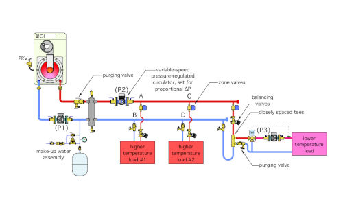
I recently had an inquiry from a designer who needed to combine some high temperature loads with low temperature loads. The latter would be supplied through a 3-way motorized mixing valve. Whenever a mixing valve is used, there must be a circulator between the mixing valve and the low temperature heat emitters. Wanting to hydraulically separate this circulator from the main system circulator, the designer proposed a piping topology very similar to that shown in Figure 1.

G&F Figure 1


The Fix:  

Although the closely-spaced tees at points E and F in Figure 1 will provide hydraulic separation between circulators (P2) and (P3), the overall piping arrangement is going to create some undesirable conditions. 

 The piping on the right side of the hydraulic separator is neither a “2-pipe” system, nor a primary/secondary system. Trying to morph these two piping topologies together is not a good idea.

The maximum differential pressure available to drive flow through the higher temperature load No. 1 will be the pressure differential developed between points A and B due to the head loss around the “loop” serving the closely-spaced tees. 

Likewise, the maximum pressure differential available to drive flow through the higher temperature load No. 2 will be that caused by the head loss between points C and D.  These pressure differentials may or may not be able to create the intended flow rates through the higher temperature loads. 

If the piping path around the “loop” is short, there won’t be much differential pressure. Furthermore, these pressure differentials will also change depending on which of the two high temperature loads is active. It’s not a stable situation.

A more stable situation can be created by eliminating the “loop” portion of the piping, and creating a “crossover” for the lower temperature load, as shown in Figure 2.

G&F Figure 2

The overall piping topology is now a “2-pipe” header system. All three loads connect across the headers.  This is no more “primary loop.” All three load branches have a balancing valve to properly proportion flow rate between them.

Circulator (P2) has been converted to a variable-speed pressure-regulated circulator operating in proportional differential pressure mode. This mode will keep the differential pressure across each branch relatively stable regardless of which branches are operating. It will also significantly reduce the pumping energy required by the system. 

The closely-spaced tees in the crossover for the low temperature load provide hydraulic separation between circulators (P2) and (P3). 

Other glitches that have been corrected:

  1. Adding a pressure relief valve to the boiler.
  2. Adding a purging valve to the boiler circuit.
  3. Adding a make-up water system and expansion tank.
  4. Showing the purging valve on high temperature load #1 in the correct orientation.
  5. Adding a purging valve downstream of closely-spaced tees for low temperature load.


Download The Glitch and Fix: February 2020 in pdf form.

KEYWORDS: circulators piping

Share This Story

Looking for a reprint of this article?
From high-res PDFs to custom plaques, order your copy today!

Recommended Content

JOIN TODAY
to unlock your recommendations.

Already have an account? Sign In

  • 2025 Next Gen ALL-STARS hero 1440

    2025 Next Gen All Stars: Top 20 Under 40 Plumbing Professionals

    This year’s group of NextGen All-Stars is full of young...
    Plumbing & Mechanical Contractor
    By: Kristen R. Bayles
  • Worker using the Milwaukee Tool SWITCH PACK drain cleaner

    Pipeline profits: Drain cleaning, pipe inspection create opportunities

    Drain cleaning and inspection services offer lucrative...
    Plumbing News
    By: Nicole Krawcke
  • Uponor employee, Arturo Moreno

    The reinvestment in American manufacturing and training

    Plumbing & Mechanical Chief Editor Nicole Krawcke and...
    Plumbing News
    By: Nicole Krawcke and Natalie Forster
Manage My Account
  • eNewsletters
  • Online Registration
  • Subscription Customer Service
  • eMagazine
  • Manage My Preferences

More Videos

Popular Stories

Hot water pipes

Campus shutdown at Oakland University exposes hidden risks of aging hot-water infrastructure

Floor heating manifold cabinet with flowmeter and PEX pipe.

Elegance extended: How to use the homerun system of connecting heat emitters

Industrial pressure gauge on a tank.

From cutting edge to classic: How to modernize outdated pneumatic control systems

Poll

Will business be up or down in 2025?

Do you anticipate business in 2025 to be up or down in comparison to 2024?
View Results Poll Archive

Products

The Water Came To A Stop

The Water Came To A Stop

See More Products
eBook | 2025 Radiant & Hydronics All Stars

Related Articles

  • Glitch and Fix Figure 1

    The Glitch and Fix: Mixed mode

    See More
  • The Glitch - April

    The Glitch & The Fix: Mixed results

    See More
  • glitch-fix-feature

    The Glitch & The Fix: Circulator problems

    See More

Related Products

See More Products
  • The ACCA Job Safety (1).jpg

    The ACCA On-The-Job Safety Handbook (Pack of 5)

  • what hydronics taught holohan.jpg

    What Hydronics Taught Holohan: A Memoir of Life in the Heating Industry

  • 51CHeeKvw4L._SX322_BO1,204,203,200_.jpg

    Hydronic Radiant Heating: A Practical Guide for the Nonengineer Installer

See More Products
×

Keep your content unclogged with our newsletters!

Stay in the know on the latest plumbing & piping industry trends.

JOIN TODAY!
  • RESOURCES
    • Advertise
    • Contact Us
    • Directories
    • Store
    • Want More
    • Supply House Times
  • SIGN UP TODAY
    • Create Account
    • eMagazine
    • eNewsletter
    • Customer Service
    • Manage Preferences
  • SERVICES
    • Marketing Services
    • Reprints
    • Market Research
    • List Rental
    • Survey/Respondent Access
  • STAY CONNECTED
    • LinkedIn
    • Facebook
    • Instagram
    • YouTube
    • X (Twitter)
  • PRIVACY
    • PRIVACY POLICY
    • TERMS & CONDITIONS
    • DO NOT SELL MY PERSONAL INFORMATION
    • PRIVACY REQUEST
    • ACCESSIBILITY

Copyright ©2025. All Rights Reserved BNP Media.

Design, CMS, Hosting & Web Development :: ePublishing