search
cart
facebook instagram twitter linkedin youtube
  • Sign In
  • Create Account
  • Sign Out
  • My Account
  • NEWS
  • PRODUCTS
    • FEATURED PRODUCTS
  • CONTRACTORS
    • BATH & KITCHEN PRO
    • BUSINESS MANAGEMENT
    • HIGH EFFICIENCY HOMES
    • TECHNOLOGY
    • WATER TREATMENT
    • PMC COLUMNS
      • Dave Yates: Contractor’s Corner
      • John Siegenthaler: Hydronics Workshop
      • Kenny Chapman: The Blue Collar Coach
      • Matt Michel: Service Plumbing Pros
      • Scott Secor: Heating Perceptions
  • ENGINEERS
    • CONTINUING EDUCATION
    • DECARBONIZATION | ELECTRIFICATION
    • FIRE PROTECTION
    • GEOTHERMAL | SOLAR THERMAL
    • PIPING | PLUMBING | PVF
    • PME COLUMNS
      • Christoph Lohr: Strategic Plumbing Insights
      • David Dexter: Plumbing Talking Points
      • James Dipping: Engineer Viewpoints
      • John Seigenthaler: Renewable Heating Design
      • Lowell Manalo: Plumbing Essentials
      • Misty Guard: Guard on Compliance
  • RADIANT & HYDRONICS
    • RADIANT COMFORT REPORT
    • THE GLITCH & THE FIX
  • INSIGHTS
    • CODES
    • GREEN PLUMBING & MECHANICAL
    • PROJECT PROFILES
    • COLUMNS
      • Codes Corner
      • Natalie Forster: Editorial Opinion
      • Guest Editorial
  • MEDIA
    • EBOOKS
    • PODCASTS
    • VIDEOS
    • WEBINARS
  • RESOURCES
    • INDUSTRY CALENDAR
    • DIRECTORIES
    • PM BOOKSTORE
    • CE CENTER
    • MARKET RESEARCH
    • CLASSIFIEDS
  • EMAGAZINE
    • EMAGAZINE
    • ARCHIVE ISSUES
    • CONTACT
    • ADVERTISE
    • PME EMAGAZINE ARCHIVES
  • SIGN UP!
Plumbing & Mechanical ContractorRadiant & HydronicsThe Glitch & The Fix

The Glitch & The Fix: Circulator problems

glitch-fix-feature
September 28, 2023
✕
Image in modal.

The Glitch:

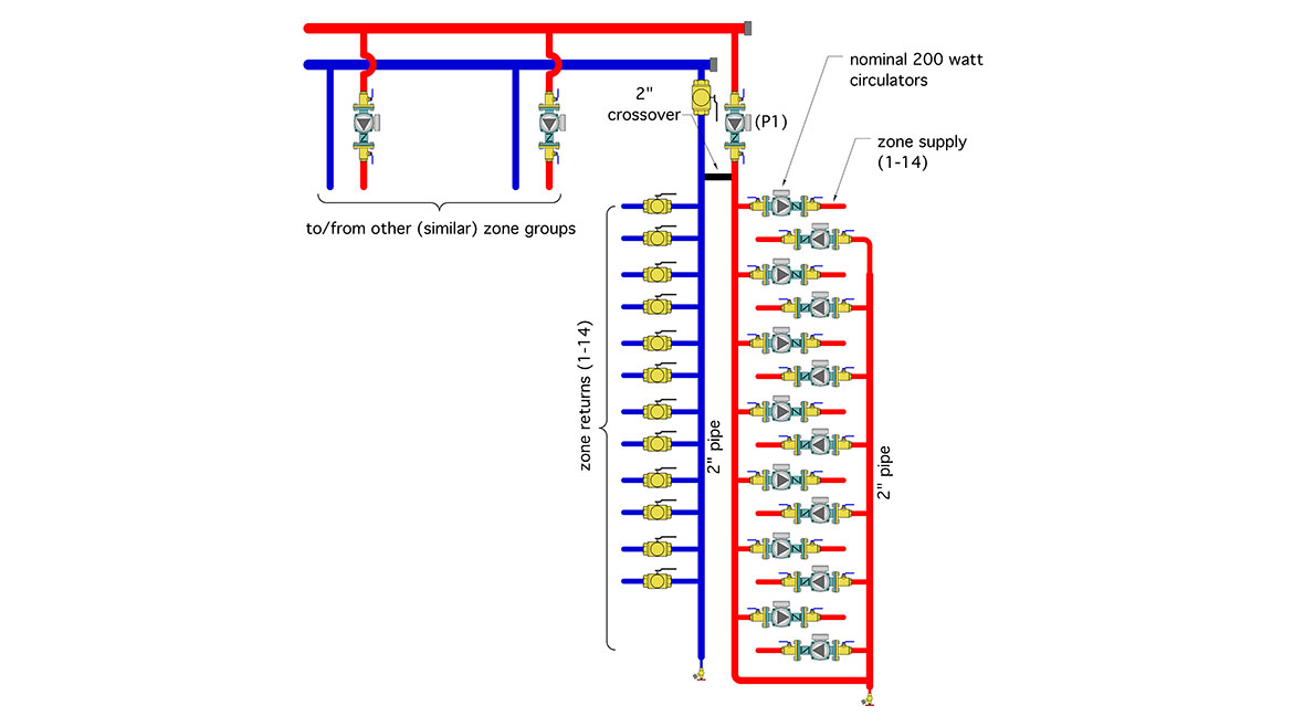
The piping shown in Figure 1 is a partial representation of an actual installation. The portion of the system shown on the right side supplies 14 independently controlled zones, with 14 circulators each having a nominal 200-watt power input. There’s another circulator (P1) piped in above the zone circulators. There’s also a crossover pipe between the supply and return sides of this piping assembly. The occupants of the large home where this system is installed state that when only 2 or 3 zones are operating, comfort is fine. However, as more zone circulators turn on, there’s less and less heat output from all the active zones. Can you diagnose why this is happening, and suggest alternate methods for constructing this portion of the system?

Figure 1

PM 0923 Glitch and Fix Figure 1

The Issues:

If all the circulators are operating, which should be assumed as possible under design load conditions, the electrical power demand is cringe-worthy (14 zone circulator x 200 watts = 2,800 watts = 2.8 KW = 9,560 Btu/h). Furthermore, that power demand is only about half of the total possible demand of the system based on how the other zone groups are constructed. Think about it, on a mild day in spring or fall, just turn off the boilers, turn on all the circulators, and let fluid friction heat the house. Surely we can do better in terms of power input to distribute heat — even in large houses.

I would also question if 2” copper piping for the vertical headers is sufficient for the anticipated flow rates if most, or all, circulators were operating. Granted, that condition would not occur often, but when it did, the flow velocity in the left side vertical supply header could be high enough to cause a significant loss of hydraulic separation between the circulators, which would lead to significant flow rate variation in the zones. The greater the number of active zones, the greater this variation. 

It’s also likely that the total zone flow rate will be higher than the flow rate through circulator (P1). This causes some of the flow returning from the zones to pass through the bypass pipe and mix with the hot water supplied through circulator (P1). This mixing lowers the temperature to the zone circulators, and is likely the cause of the reduced heat output as more zone circulators are operating.

Other issues include a lack of purging valves on the return side of each zone circuit, and circulator inlets placed very close (e.g., less than 10 pipe diameters) from header tees.

The Fixes

One alternate configuration is shown in Figure 2.

Figure 2

PM 0923 Glitch and Fix Figure 2

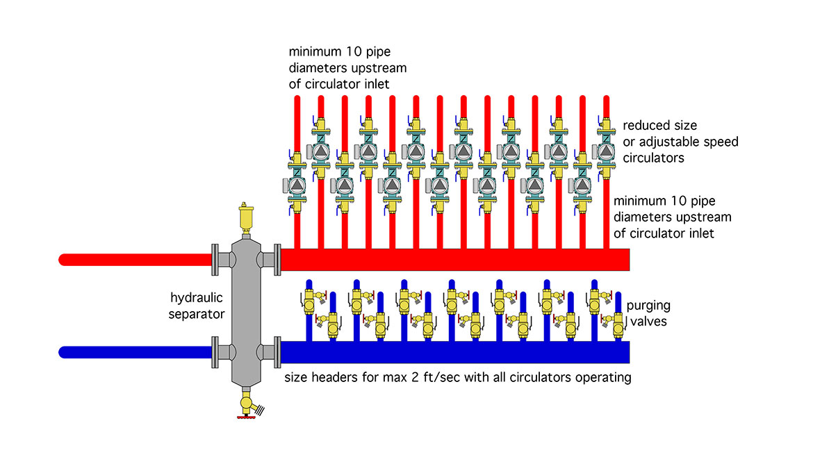
This alternative stays with zone circulators, but assumes downsizing those circulators, or using speed-adjustable circulators, to reduce power consumption.

A hydraulic separator is used in combination with upsized supply and return headers. The separator isolates the flow dynamics of the zones from that of the circulator creating flow to this subassembly. The generously sized header “reinforces” the concept of low-pressure drop in the common piping — the fundamental concept behind hydraulic separation.

Figure 3 shows another alternative based on a single variable speed circulator and zone valves.

Figure 3

PM 0923 Glitch and Fix Figure 3

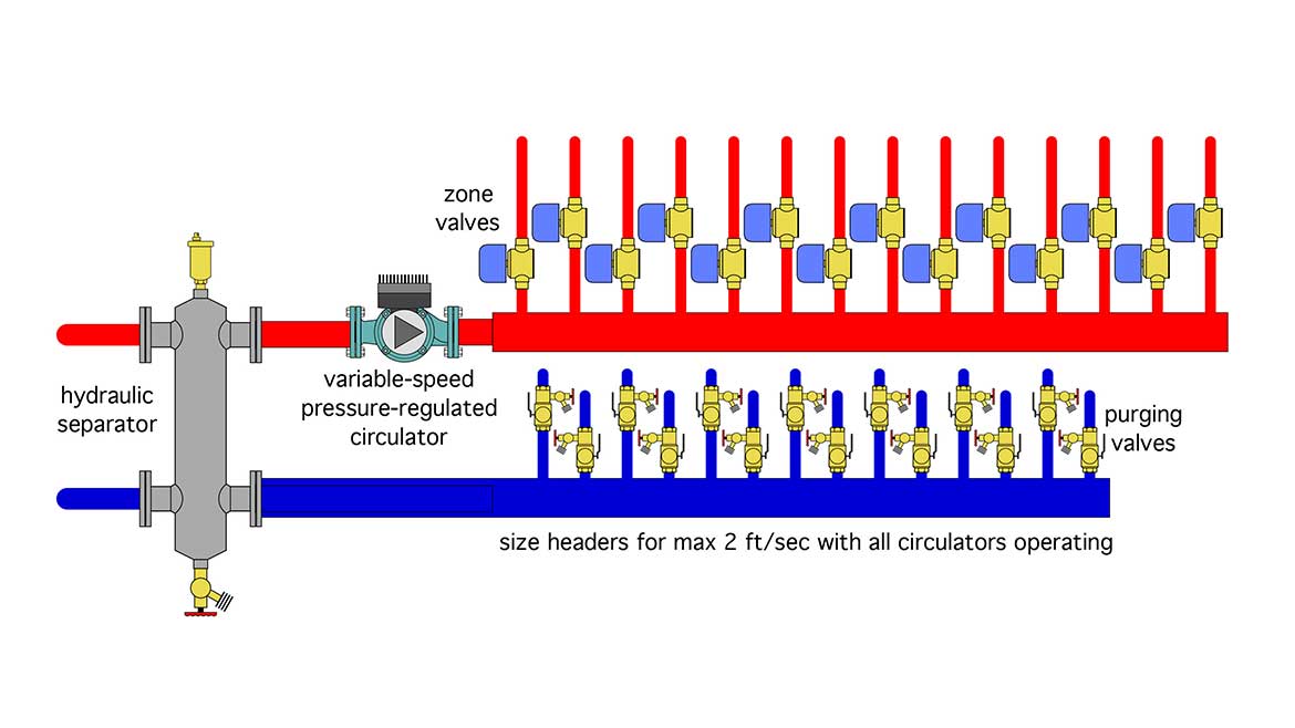
The hydraulic separator again isolates the flow dynamics of the 14 zone circuits from those created in other portions of the system. It allows the variable speed circulator to operate over a wide speed range without interference.

≫ More The Glitch & The Fix

The piping between the hydraulic separator and headers should be as large as possible to minimize pressure drop. It’s OK to go back up in pipe size after the circulator to keep the flow velocity in the main header no higher than 2 feet per second.

Another possibility

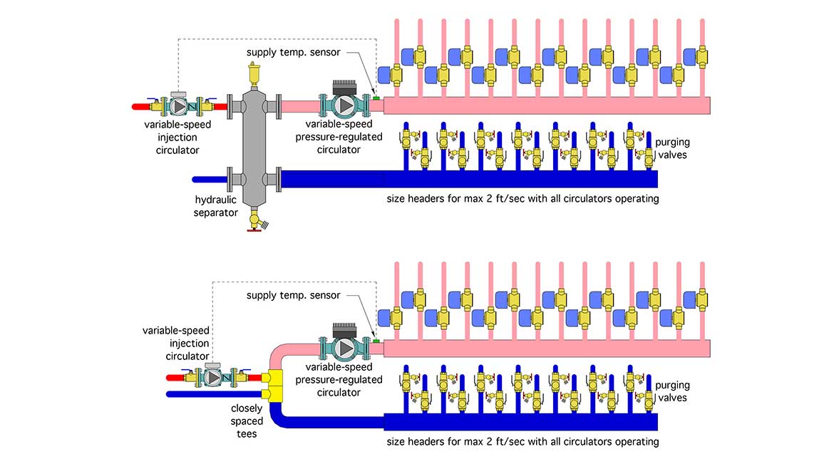
I’ve not seen the final details used in this system.  Given what is known, there’s a possibility that circulator (P1) in Figure 1 was intended to be a variable speed injection circulator. Its speed at any time would determine the flow rate of hot boiler injected into the header below and thus the reduced supply water temperature to the 14 zones. Assuming this was the intent, either of the two piping configurations shown in Figure 4 would provide better hydraulic separation between the injection circulator and distribution circulator.

Figure 4

KEYWORDS: circulators piping toilet

Share This Story

Looking for a reprint of this article?
From high-res PDFs to custom plaques, order your copy today!

Recommended Content

JOIN TODAY
to unlock your recommendations.

Already have an account? Sign In

  • 2025 Next Gen ALL-STARS hero 1440

    2025 Next Gen All Stars: Top 20 Under 40 Plumbing Professionals

    This year’s group of NextGen All-Stars is full of young...
    Plumbing & Mechanical Contractor
    By: Kristen R. Bayles
  • Worker using the Milwaukee Tool SWITCH PACK drain cleaner

    Pipeline profits: Drain cleaning, pipe inspection create opportunities

    Drain cleaning and inspection services offer lucrative...
    Green Plumbing and Mechanical
    By: Nicole Krawcke
  • Uponor employee, Arturo Moreno

    The reinvestment in American manufacturing and training

    Plumbing & Mechanical Chief Editor Nicole Krawcke and...
    Plumbing News
    By: Nicole Krawcke and Natalie Forster
Manage My Account
  • eNewsletters
  • Online Registration
  • Subscription Customer Service
  • eMagazine
  • Manage My Preferences

More Videos

Popular Stories

Hot water pipes

Campus shutdown at Oakland University exposes hidden risks of aging hot-water infrastructure

Floor heating manifold cabinet with flowmeter and PEX pipe.

Elegance extended: How to use the homerun system of connecting heat emitters

Industrial pressure gauge on a tank.

From cutting edge to classic: How to modernize outdated pneumatic control systems

Poll

Will business be up or down in 2025?

Do you anticipate business in 2025 to be up or down in comparison to 2024?
View Results Poll Archive

Products

The Water Came To A Stop

The Water Came To A Stop

See More Products
eBook | 2025 Radiant & Hydronics All Stars

Related Articles

  • The Glitch and The Fix Figures 1 and 2

    The Glitch & The Fix: Identify the flow problems

    See More
  • glitch-fix-feature

    The Glitch + The Fix: Plethora of problems

    See More
  • Figure 1 is a sketch of the flow problems of the current plumbing system.

    Hydronic heating glitch solved: Why adding a circulator won't fix primary loop flow issue

    See More

Related Products

See More Products
  • pocketfullsteamproblm.gif

    A Pocketful of Steam Problems (with solutions!)

  • The ACCA Job Safety (1).jpg

    The ACCA On-The-Job Safety Handbook (Pack of 5)

  • Classic Hydronics - How To Get The Most From Those Older Hot-Water Heating Systems

See More Products
×

Keep your content unclogged with our newsletters!

Stay in the know on the latest plumbing & piping industry trends.

JOIN TODAY!
  • RESOURCES
    • Advertise
    • Contact Us
    • Directories
    • Store
    • Want More
    • Supply House Times
  • SIGN UP TODAY
    • Create Account
    • eMagazine
    • eNewsletter
    • Customer Service
    • Manage Preferences
  • SERVICES
    • Marketing Services
    • Reprints
    • Market Research
    • List Rental
    • Survey/Respondent Access
  • STAY CONNECTED
    • LinkedIn
    • Facebook
    • Instagram
    • YouTube
    • X (Twitter)
  • PRIVACY
    • PRIVACY POLICY
    • TERMS & CONDITIONS
    • DO NOT SELL MY PERSONAL INFORMATION
    • PRIVACY REQUEST
    • ACCESSIBILITY

Copyright ©2025. All Rights Reserved BNP Media.

Design, CMS, Hosting & Web Development :: ePublishing