The Glitch: Thermal bullying

The Glitch:
A contractor is asked to design a hydronic heating system for a modest, super-insulated house in a cold Northern climate. The home’s design load is only 18,000 Btu/h. The owners are planning to install a 12 KW solar photovoltaic electrical system. The local utility offers net metering, allowing surplus electrical power to be sent to the grid at full retail rate. Some of that “banked” electrical energy can be used during nighttime or on low solar gain days.
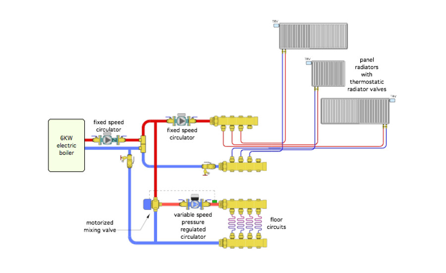
The contractor selects a 6 KW (20,500 Btu/h) electric boiler for the heat source. That boiler will supply floor heating in the basement slab, and three panel radiators on the main floor. The system will be filled with an anti-freeze solution to protect it against prolonged power outages. The system is piped as shown in Figure 1.
The owners report that although the system is generally comfortable, they’ve noticed the main living room areas served by the panel radiators get cool and remains that way for two or three hours whenever they turn up the basement thermostat.
Can you determine why this is happening, propose a way to fix it and identify some other errors in the proposed drawing?
> Figure 1:
The Fix:
The temporary loss of comfort in the rooms heated by the panel radiators is caused by an unanticipated drop in supply water temperature due to the high thermal mass of the floor slab scarfing up heat at a rate much higher than its steady state output rate. This happens whenever the basement thermostat setting is increased. The cooler the slab, the greater its ability to temporarily “steal” heat from the remainder of the system. This causes the water temperature in the entire system to drop — a transient condition caused by the system attempting to establish thermal equilibrium between heat input and heat output rates.
The solution is to use a controller on the 3-way motorized mixing valve that can sense what the controller understands to be “boiler return temperature.” Most controllers for motorized mixing valves have this ability. It’s intended to protect a conventional boiler against sustained flue gas condensation, especially in systems with high mass, low temperature heat emitters. Whenever the controller senses that the “boiler return temperature” is about to drop below a present minimum value, such as 130° F, the hot port of the mixing valve reduces its intake of hot water. The objective is to prevent the “boiler inlet temperature” from dropping further (e.g., where sustained flue gas condensation could occur).
So why are the words “boiler return temperature” in quotes? Because that’s not what is going to be sensed in this application. There’s no need to protect an electrical boiler against flue gas condensation. Fortunately, the same control logic can be used to throttle down the hot water intake of the motorized mixing valve so the system water temperature remains high enough for proper heat output at the panel radiators. Just install the “boiler return temperature” sensor as shown in Figure 2, and set the mixing valve controller for a minimum temperature that allows adequate heat output from the panel radiators.
> Figure 2:

Other issues for the system in Figure 1 include:
-
There’s no expansion tank on the system;
-
There’s no pressure relief valve;
-
There’s no way to easily fill the system with antifreeze solution or get the air out;
-
There is no central air separator;
-
The variable speed circulator is more appropriate for the panel radiator subsystem since the thermostatic valves will be opening, closing and modulating. There’s really no need for a variable speed circulator on the radiant panel subsystem since there are no individual circuit valves;
-
The cool water from the radiant manifold should not go back to the boiler secondary circuit. See how this is corrected in Figure 2; and
-
Both purging valves are installed backwards.
Please read here to view The Glitch and Fix: May 2019 in pdf form.
Looking for a reprint of this article?
From high-res PDFs to custom plaques, order your copy today!