The Glitch: Follow the arrows

The Glitch:
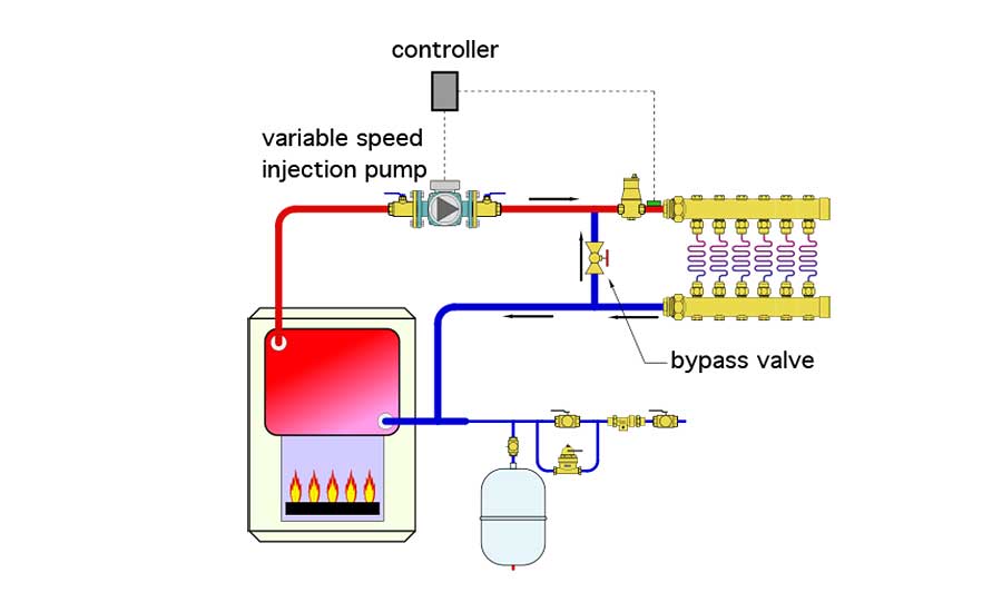
An installer is planning to combine a cast iron boiler with a low temperature radiant floor panel. He knows that the boiler is not “flow sensitive.” It can operate with very little if any flow passing though it. The piping he plans is shown in figure 1. His thinking is that some of the cool water returning from the radiant panel circuits will pass upward through the “bypass valve” and mix with hot water from the boiler to create lower temperature supply water. He reasons that the faster the variable speed injection pump runs the higher the water temperature supplied to the radiant panel circuits. Can you spot at least 4 errors or missing details in this schematic?
Figure 1:
The Fix:
When flow gets “pushed out” of a circulator, all it cares about is getting back to the inlet of that circulator. It will do so through the path(s) of least resistance. In this system most of the flow from the circulator will pass downward through the bypass valve, and back into the boiler. A very small flow rate will pass into the radiant panel circuits. However, that flow rate will be much too low to supply the necessary heat transfer. This will show up as a very high ∆T across the radiant panel circuits. Whenever mixing is necessary, the circulator carrying heat to the heat emitter(s) must be located between those emitters and the mixing assembly.
Other errors include:
-
Air separator on higher pressure side of circulator.
-
No purging valves for expediting air removal when filling the system.
-
Lack of a pressure relief valve on boiler.
-
Supply temperature sensor upstream of the supposed mixing point.
-
No means of protecting the cast iron boiler from low temperature inlet water which could cause sustained flue gas condensation.
Figure 2 shows the proper installation of a variable speed injection pump. Note that there is a drop of at least 18 inches between the tees that connect the injection risers to the boiler loop, and those that connect them to the low temperature distribution loop.
Figure 2:
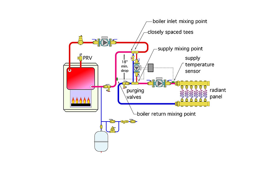 Also notice the boiler inlet temperature sensor, which allows the injection mixing controller to slow the injection circulator when necessary to keep the boiler inlet temperature high enough to prevent sustained flue gas condensation.
Please read here to view The Glitch & Fix: September 2018 in pdf form.
Looking for a reprint of this article?
From high-res PDFs to custom plaques, order your copy today!


.jpg")
