Properly sizing and operating circulators
Reducing head loss reduces the kWh of electrical energy required to operate them.

Figure 1. Assuming the 200’ x 3/4” copper tube circuit was carrying water at an average temperature of 120° F it would have the circuit head loss curve shown in Figure 1. Photo credit: John Siegenthaler
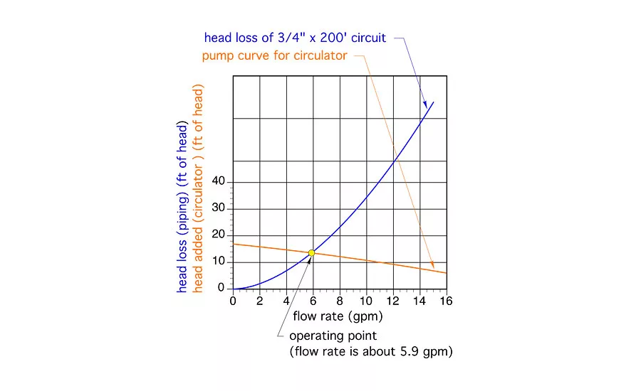
Figure 2 shows the same head loss curve along with the pump curve of a typical small wet rotor “zone” circulator. Photo credit: John Siegenthaler
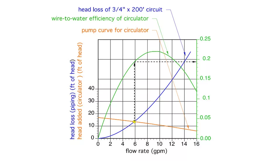
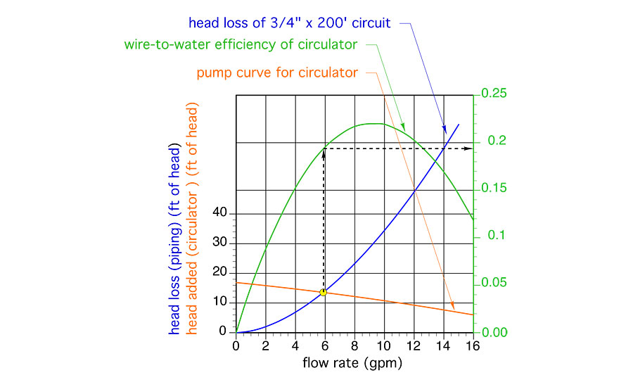
Figure 3 shows the same curves as Figure 2, but adds another curve, shown in green, representing the “wire-to-water efficiency” of the circulator. Photo credit: John Siegenthaler
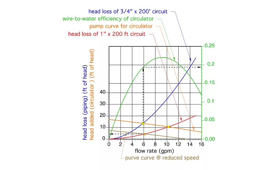
The head loss curve for a circuit constructed of 1” type M copper tubing, and having an equivalent length of 200 feet, is shown (in red) in Figure 4. Photo credit: John Siegenthaler
When designing hydronic circuits, most of us focus on what’s necessary for that circuit to absorb thermal energy at a heat source, carry it along like a conveyor belt and release that energy at one or more heat emitters. After all, that’s the principal objective of any hydronic heating system —regulating thermal energy transfer from source to load.
But thermal energy isn’t the only energy being processed in hydronic systems. Electrical energy is being converted into mechanical energy. The latter is what’s referred to as “head” in the hydronics industry. Circulators convert electrical energy into head energy.
The efficiency of that conversion can vary over a wide range, from single digits to upwards of 60%. Small wet rotor circulators operating near either end of their pump curve have very low electrical-to-head energy conversion efficiency. A larger circulator with more efficient multi-horsepower motors applied so that they operate near the middle of their pump curve represent the higher end of the efficiency range.
Head energy is eventually dissipated into heat due to friction between fluid molecules as well as friction between the fluid and surfaces it flows across.
Every hydronic heating professional understands that there’s a cost associated with operating a circulator. Every kWh of electrical energy “fed” to the circulator comes at a price. In some areas of the US it’s only a few cents. In other locations, such as remote villages in Alaska where diesel fuel is trucked in to power generators, it’s over $0.50 per kWh.
It’s not hard to understand that reducing head loss in hydronic systems reduces the kWh of electrical energy required to operate them. But do we really think about this enough as we design?
Head converted to dollars
Imagine a closed hydronic circuit constructed of type M copper tubing and having an equivalent length of 200 feet. Assume this circuit needs to convey a flow rate of 6 gpm along a round trip between a mechanical room and the coil of an air handler. What tube size would you normally select for this circuit?
The usual sizing criteria for copper tubing in smaller hydronic systems is to keep the flow velocity no higher than 4 feet per second. That flow velocity corresponds to a flow rate of 6.4 gpm in 3/4” type M copper tubing, so 3/4” is likely the common size selected to handle this flow requirement. My guess is that many of you didn’t have to consult a flow velocity versus flow rate chart in order to select a 3/4” tube for this flow rate. You just knew from previous experience that a 1/2” tube was too small and a 1” tube was “overkill” for 6 gpm, so you picked the size in between.
Let’s work in a few simple calculations to see if that was a good choice.
Assuming the 200’ x 3/4” copper tube circuit was carrying water at an average temperature of 120° F it would have the circuit head loss curve shown in Figure 1.
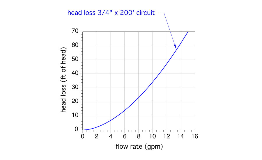
You can make a circuit head loss curve like this by graphing head loss versus flow rate values that can be looked up in many design references. The data in these references is usually listed as feet of head loss per 100 feet of pipe. Since our assumed circuit has an equivalent length of 200 feet, we can just double the head loss values, plot the points on the graph and draw a smooth curve through them.
Figure 2 shows the same head loss curve along with the pump curve of a typical small wet rotor “zone” circulator. The point where these two curve cross is called the operating point. It’s where the head energy supplied to the water by the circulator exactly matches the head energy being dissipated from the water by friction.
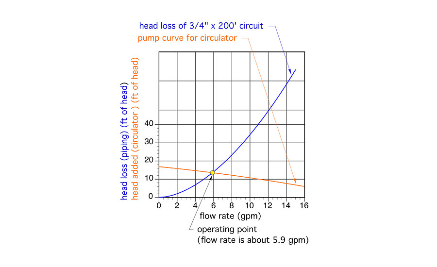
If you draw a line straight down from the operating point you can find the flow rate the system will operate at. In this case it’s about 5.9 gpm. Since this flow rate is very close to the target flow rate of 6 gpm, this circulator would be an acceptable selection.
Figure 3 shows the same curves as Figure 2, but adds another curve, shown in green, representing the “wire-to-water efficiency” of the circulator (e.g., the efficiency at which the circulator converts electrical energy into head energy). The efficiency values are shown a decimal percentages on the graph’s right vertical axis.
At the operating point of 5.9 gpm, the circulator has a wire-to-water efficiency of 19.5%. That value is not very impressive, but it also not far below the peak wire-to-water efficiency of this circulator, which is about 22%.
Input > Output
The owner of a hydronic system doesn’t pay, at least directly, for head energy. They pay for the electrical energy needed to operate the circulator that imparts head energy to the water. You can estimate that cost by considering the power demand of the circulator and the total on time of the circulator.
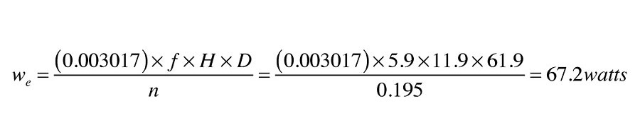
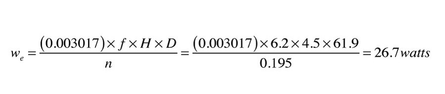
The electrical power input to a circulator can be estimated using Formula 1

Where:
we = electrical power required by circulator (watts)
f = flow rate in circuit (gpm)
H = head loss of circuit while operating at flow rate (f) (feet of head)
D = density of fluid circulating in system (lb/ft3)
n = wire-to-water efficiency of circulator operating at flow (f) and head (H) (decimal %)
For the operating point shown in Figure 3 the estimated electrical input to the circulator would be estimated at:
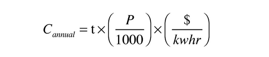
 The annual operating cost of any device requires a specific power input and operates for a known number of hours can be easily calculated using this formula:
 Where:
Cannual = annual operating cost ($/year)
t = number of hours pump is on per year (hours/year)
P = input power to circulator (watts)
$/kwhr = cost of electricity (dollar/kwhr)
If the circulator represented in Figure 3 operated for 3,000 hours per year in a location where electricity costs $0.15/kWh, its annual operating cost would be: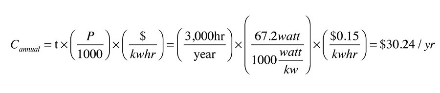
Consider the options
How would this operating cost change if the circuit was constructed of 1” copper tubing rather than 3/4” copper tubing? I’m sure most of you know it would go down, but by how much, and is the reduction worth considering? Back to the math for some answers.
The head loss curve for a circuit constructed of 1” type M copper tubing, and having an equivalent length of 200 feet, is shown (in red) in Figure 4.
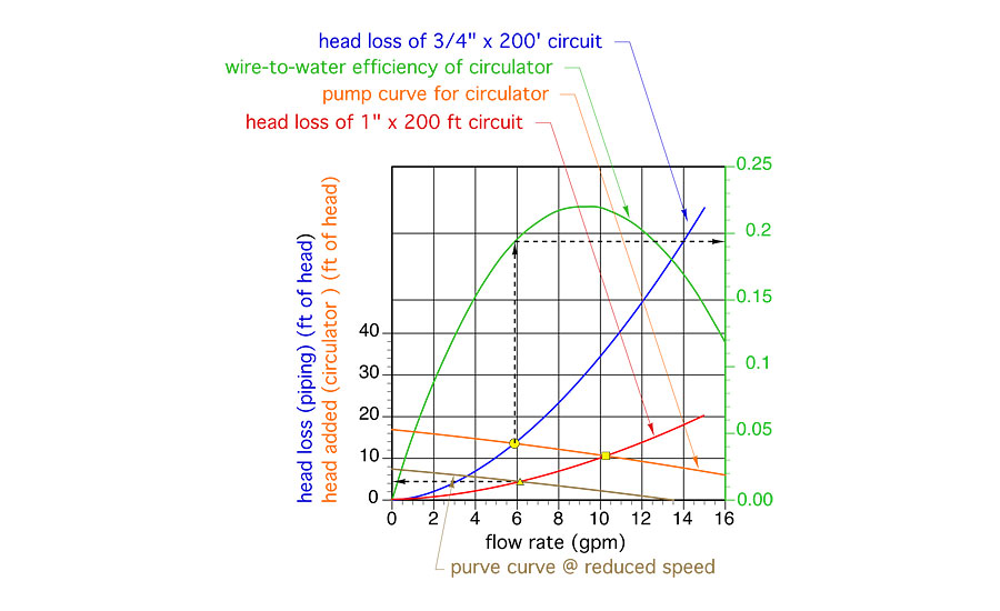
If the same circulator, operating at the same speed setting, was used in this circuit, the flow rate would increase to about 10.2 gpm (as shown by the yellow square at the new operating point in Figure 4). But remember, the target flow rate was 6 gpm. We don’t need to operate the circuit at higher flow rates. So, the designer now looks for a different circulator, or looks at how the pump curve would change if the currently selected circulator could operate at a lower speed.
Assume the circulator’s speed could be reduced so that its new pump curve is the brown curve in Figure 4. The intersection between the circuit head loss curve for the 200 feet x 1” Type M copper circuit and the new pump curve occurs at a flow rate of about 6.2 gpm. This is again close enough to the target flow rate to be an acceptable option.
The head loss at the operating point shown by the yellow triangle in Figure 4 is now about 4.5 feet. Assuming the circulator’s wire-to-water efficiency remains essentially the same at the reduced speed, the electrical input to the circulator is now estimated as:
 The annual operating cost of the circulator under the same conditions as previously assumed (3,000 hours per year and $0.15/kWh) would now be $12.02.
The 1” tubing combined with operating the circulator at lower speed produces about the same flow rate using 60 percent less electrical electrical energy.
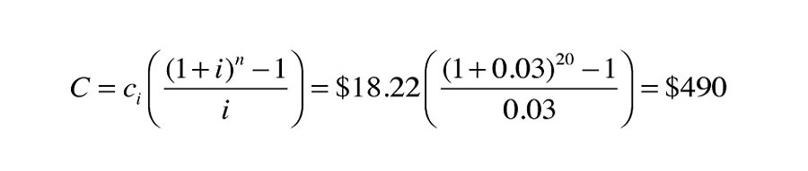
Although a 60% reduction in energy use should get anyone’s attention, you may still think that the difference in operating cost of $18.22 per year is trivial. However, little differences add up over time. If we assumed that the cost of electrical energy increased at 3% per year, and totaled this difference in operating cost over a 20 year period, the total operating cost savings for using 1” rather than 3/4” tubing would be:
 Obviously it costs more to construct the circuit using 1” rather than 3/4” tubing, and this added cost would have to be deducted from the life cycle saving associated with lower operating cost. Still, it’s likely that the “net” savings in operating cost would exceed the added installation cost within 20 years, and perhaps much sooner in areas where electricity is more expensive.
Be vigilant
If your goal is to maximize the technical advantages of hydronic versus air-based heat delivery, you should always be looking for ways to reduce the pumping power requirements of your systems.
Consider the head loss characteristics of the heat sources, heat emitters, dirt separators, mixing valves, heat exchangers and other components you select. The lower they are, the lower the potential operating cost of the system. Don’t “settle” on high head loss components if there are competitive options available with lower head loss.
Transition your designs to what soon will be the “new normal” of higher efficiency circulators with electronically commutated motors.
The automotive and aerospace industries has been working for decades to reduce the drag of vehicles they produce. Lower drag results in high fuel efficiency, and both of these industries have achieved major advances in fuel efficiency compared to 40 years ago.
The hydronic equivalent of this is would be designing components and circuits with lower head loss. If you’re a manufacturer, don’t take a dismissive attitude that installers will just have to use larger circulators to accommodate the head loss requirements of your hardware, and thus it’s not “your problem.”
For example, some mod/con boilers require dedicated circulators that draw over 200 W. The sole function of that circulator is to move flow through the boiler at an acceptable rate. Separate circulators are required for the distribution system.
Several decades ago there was no need for dedicated boiler circulators in single boiler systems. The head loss of a cast iron sectional boiler was low enough that the distribution circulators could easily move flow through the entire system.
That’s still the case for cast-iron boilers as well as some contemporary hydronic heat sources where low head loss was an integral part of the design objectives. In other cases, it appears that hydraulic efficiency has been willingly sacrificed for gains in thermal efficiency, reduced material, or smaller size.
Such tradeoffs aren’t limited to boilers. Some water-to-refrigerant heat exchangers used in geothermal heat pumps also have a voracious appetite for head energy. Combine this with long earth loop circuits with minimal pipe sizes, and the low wire-to-water efficiency of small wet rotor circulators with PSC motors, and you may need upwards of 1,000 watts of circulator input power just to move heat from the ground to a residential size geothermal heat pump.
The unimpressive hydraulic power requirement of geothermal heat pump systems is seldom discussed. Instead, the geo-narrative focuses on impressive values of thermal efficiency such as coefficient of performance (COP) and energy efficiency ratio (EER). In the end, the owner of that heat pump system doesn’t pay for COP or EER. They pay for kWh, whether they go to the compressor, the earth loop circulator(s) or other electrically operated hardware in the system.
As you design hydronic system, remember: Head energy is a terrible thing to waste.
To read Siegenthaler’s article in pdf form, please see here.
Looking for a reprint of this article?
From high-res PDFs to custom plaques, order your copy today!


