Options for achieving hydraulic seperation between circulators
Keeping the peace.

The junction between each secondary circuit and the primary loop consisted of a pair of closely spaced tees as shown in Figure 1. Graphics credit: John Siegenthaler

However, primary/secondary piping is not the only way to achieve hydraulic separation, as depicted in Figure 2. Graphics credit: John Siegenthaler

The spherical header shown in Figure 3 would be a close approximation of this ideal concept. Graphics credit: John Siegenthaler

Instead, we approximate the favorable fluid mechanics offered by the spherical header concept using standard hardware that looks good and lays up neatly in a mechanical room, as depicted in Figure 4. Graphics credit: John Siegenthaler
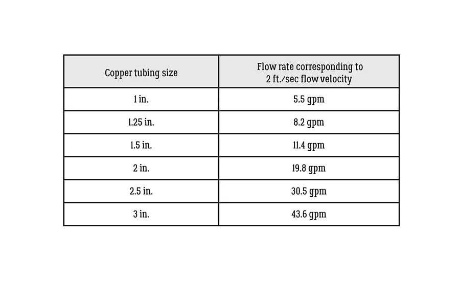
Figure 5 shows a table that lists the flow rates corresponding to flow velocities of 2 ft. per second for type M copper tube. Graphics credit: John Siegenthaler

One arrangement that achieves this is simply connecting the headers to a low-flow resistance heat source, such as a cast-iron boiler or a tank-type hydronic heat source, as shown in Figure 6. Graphics credit: John Siegenthaler
If the heat source you want to use has higher flow resistance — as is typical of mod/con boilers with compact coil-type heat exchangers, or the coaxial heat exchangers used in some hydronic heat pumps, you can merge the headers to that heat source as shown in Figure 7. Graphics credit: John Siegenthaler
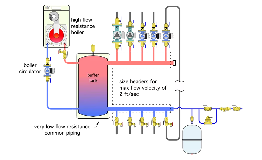
If your system needs added thermal mass to stabilize a low-mass heat source against the potential demands of a highly zoned distribution system, let a buffer tank, piped as shown in Figure 8 work in partnership with the short/fat headers to provide the hydraulic separation. Graphics credit: John Siegenthaler
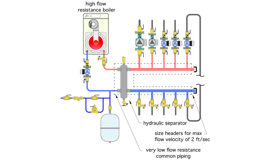
It’s also possible to use a component that, not surprisingly, is called a hydraulic separator to provide — you guessed it — hydraulic separation. The piping is shown in Figure 9. Graphics credit: John Siegenthaler
Twenty years ago, the contemporary approach to prevent interference between simultaneously operating circulators in a hydronic system was primary/secondary piping. This approach was resurrected from its inception in the 1960s for use in the multi-load systems that appeared as the modern hydronics era took root in the 1990s.
Each load circuit was called a “secondary” circuit and was powered by its own circulator. The secondary circuits merged into a common “primary” loop, which also had a dedicated circulator. The junction between each secondary circuit and the primary loop consisted of a pair of closely spaced tees as shown in Figure 1. The magic of closely spaced tees is what prevented flow in any of these circuits from interfering with flow in the others.
The magic of closely spaced tees is not hard to understand. Whenever the pressure drop in the common piping shared by two or more circuits, each with its own circulator, is very low, the ability of one circulator to affect flow in other circuits, is, for all practical purposes, eliminated. In primary/secondary systems the two closely spaced tees are the common piping between the circuits. Their side-by-side location creates very little pressure drop and thus accomplishes the physics necessary to achieve what is now commonly referred to as hydraulic separation.
Hydraulic separation is a highly desirable quality in any hydronic heating or cooling system that has two or more simultaneously operating circulators. It’s a concept that every hydronic system designer should understand in detail, and employ in every system with simultaneously operating circulators.
Beyond magic tees
Properly designed and installed primary/secondary piping provides hydraulic separation between all circuits. However, primary/secondary piping is not the only way to achieve hydraulic separation, as depicted in Figure 2.
In many cases the alternate methods for achieving hydraulic separation can provide the same benefits as classic primary/secondary piping, but in ways that simplify the system and reduce installation cost.
Hypothetical headers
Before detailing other methods of hydraulic separation, it’s important to understand the role of headers in hydronic systems. The ideal header would simply split up the flow entering it into the branch circuits attached to it with zero pressure drop. The spherical header shown in Figure 3 would be a close approximation of this ideal concept.
Imagine piping coming out of this spherical header in all directions, like a copper basketball with tubes coming out all over its surface. The water would be very content to flow through such a header, but imagine how this would look in a typical mechanical room! It would take up lots of room and be very difficult to install using standard piping practices. In short, we don’t build headers like this — not because they wouldn’t work, but because of other practical and aesthetic reasons.
Instead, we approximate the favorable fluid mechanics offered by the spherical header concept using standard hardware that looks good and lays up neatly in a mechanical room, as depicted in Figure 4.
I like to call these “short/fat” headers. Simply put, the shorter the header, and the greater its diameter, the closer it comes to approximating the spherical header. Remember, the goal is to split up the flow into the branches with as little head loss as possible.
So, here’s something that every hydronic system designer can easily remember: Short/fat headers are good, and long/skinny headers are bad!
It’s always good to keep the headers in your systems as short as practical and use a tube size that keeps the flow velocity low. I suggest sizing the header so that the maximum flow velocity within it, when all branch circuits are operating, is no higher than 2 ft. per second. Figure 5 shows a table that lists the flow rates corresponding to flow velocities of 2 ft. per second for type M copper tube.
Beyond the headers
Short/fat headers provide hydraulic separation between the circulators connected to them. These circulators can be different sizes. Some may be variable-speed circulators while others operate at fixed speeds. Hydraulic separation occurs because the head loss (and thus the pressure drop) along the length of the header is very low.
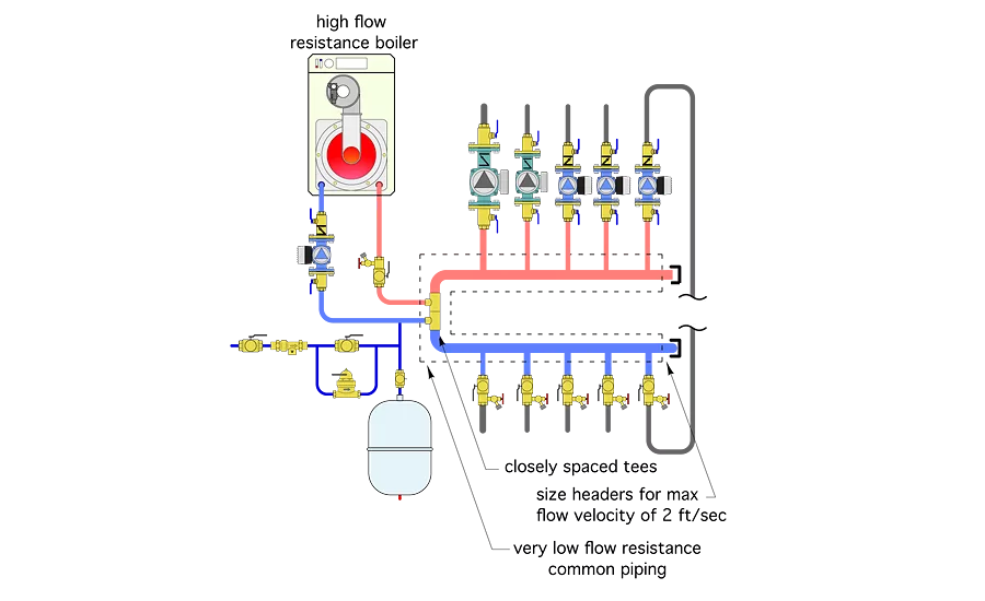
To maintain the hydraulic separation afforded by short/fat headers, it’s important that the headers connect to a piping assembly that itself creates very low head loss. One arrangement that achieves this is simply connecting the headers to a low-flow resistance heat source, such as a cast-iron boiler or a tank-type hydronic heat source, as shown in Figure 6.
Both of these heat sources create very little head loss. When combined with short/fat headers, the common piping assembly outlined with the dashed lines, creates very little head loss even when all the circulators are operating. The lack of any significant head loss in the common piping is what prevents circulators from “feeling” each other’s presence in the system. If the circulators can’t feel each other, they can’t interfere with each other, and hydraulic separation is achieved.
The piping in Figure 6 also provides the same supply water temperature to each load served by the header. This is not true with traditional primary/secondary piping where the sets of closely spaced tees are arranged in series along a common primary loop, as shown in Figure 1. The latter arrangement creates decreasing supply water temperature in the downstream circuits. Furthermore, the extent of this temperature drop is not consistent. It varies depending on which secondary circuits are operating at any given time.
If the heat source you want to use has higher flow resistance — as is typical of mod/con boilers with compact coil-type heat exchangers, or the coaxial heat exchangers used in some hydronic heat pumps, you can merge the headers to that heat source as shown in Figure 7.
The pair of closely spaced tees hydraulically separates the boiler circulator from the circulators on the header. Thus, the overall piping assembly within the dashed lines, (e.g., the common piping) has low head loss. Hydraulic separation is achieved between all the circulators.
If your system needs added thermal mass to stabilize a low-mass heat source against the potential demands of a highly zoned distribution system, let a buffer tank, piped as shown in Figure 8 work in partnership with the short/fat headers to provide the hydraulic separation.
It’s also possible to use a component that, not surprisingly, is called a hydraulic separator to provide — you guessed it — hydraulic separation. The piping is shown in Figure 9.
Along with hydraulic separation, many hydraulic separators now available in North America contain internal screens called coalescing media. These inserts enhance the ability of the device to separate microbubbles passing through the upper portion of the separator and eject them from the system. Using a hydraulic separator with a coalescing media eliminates the need for a separate high-efficiency air separator in the system.
A second media, built into the lower portion of the hydraulic separator, enhances its ability to trap dirt particles that might be riding along with the flow as it returns from the distribution system. With multiple passes, some coalescing media can separate dirt particles as small as 5 microns. These particles drop out of the active flow zone, into the lower bowl of the separator. A valve at the bottom is periodically opened to flush them from the system.
Incremental improvements
The key to hydraulic separation is keeping the pressure drop of the piping path that is common to all the circuits in the system as low as possible. The closely spaced tees used with classic primary/secondary piping are one way to do this. The alternatives presented also yield this desirable effect. They provide the same supply water temperature to each load circuit and eliminate the need for a dedicated primary loop circulator.
Given the latter characteristics, I view the alternatives as more refined approaches relative to classic primary/secondary piping. Consider using them in your upcoming systems.
This article was originally titled “Keeping the peace” in the October 2016 print edition of Plumbing & Mechanical.
Looking for a reprint of this article?
From high-res PDFs to custom plaques, order your copy today!


