Hydronics Workshop | John Siegenthaler
Options for connecting heat pumps to existing boiler systems
Tie ins
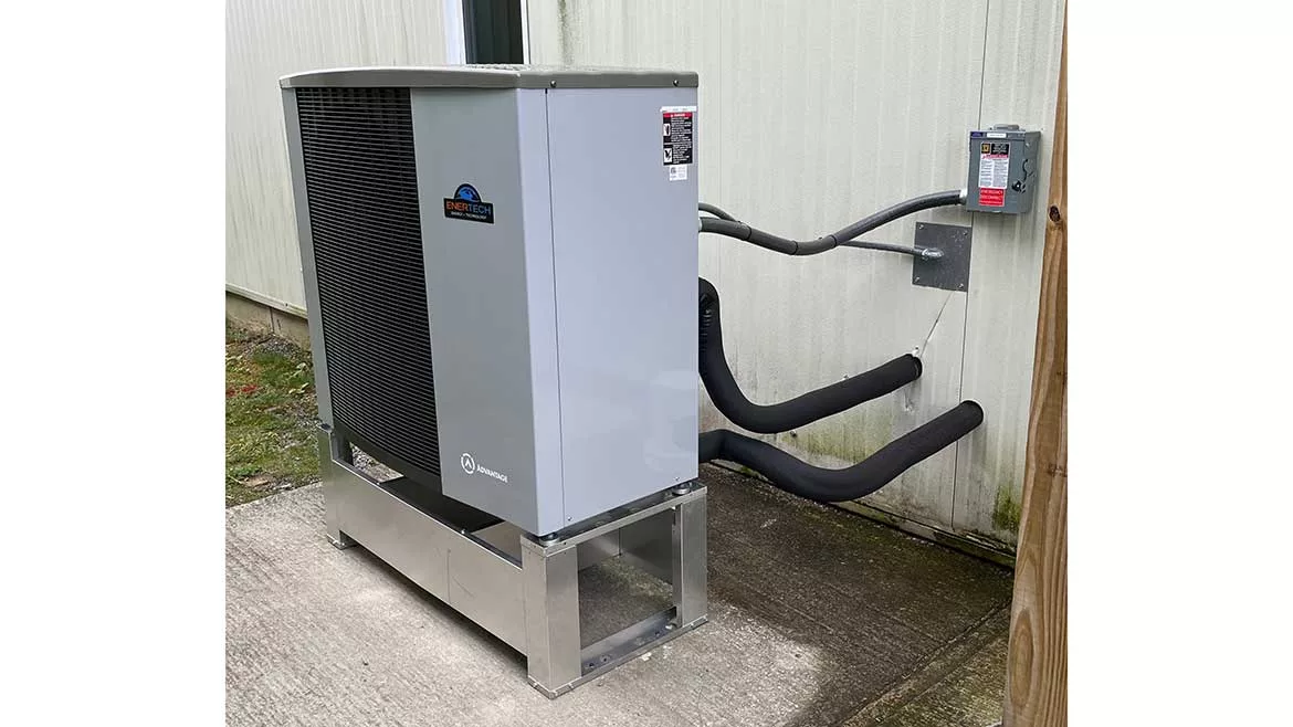
Image courtesy of the John Siegenthaler
Heat pumps, in all flavors, are continually gaining market share against all types of fossil fuel heating equipment. Regardless of how you view this trend, it’s happening, it’s not going to go away anytime soon — if ever, and it is going to reshape the hydronic heating and cooling markets in significant ways.
Like others who understand the difference between a kilowatt and a kilowatt•hour, I question the pace at which government-mandated electrification is happening. I’m skeptical that utility infrastructures are ready to handle the loads implied by the lofty electrification goals established by politicians.
But, instead of grumbling about something beyond my control, I’d rather focus on how our industry, from manufacturers to installers, can leverage what’s happening. Viewed through that prism the reshaping of the energy markets could be seen as a “gift.” It opens or enhances market opportunities that were previously not in our industry’s wheelhouse.
Examples include the opportunity to add hydronic-based cooling to the already well-established hydronic heating offering. That, in itself, is a really big deal!
The push for heat pumps also presents the opportunity to steer inquiries that start off with the goal of carbon reduction, into discussions about carbon reduction and superior comfort.
What we have to offer can open dialogue with low energy building designers, government energy planners and utility managers about concepts such as distribution efficiency, thermal storage, integration of multiple energy sources, heat metering, integrated heating/cooling DHW systems, resiliency and ways to leverage time-of-use rates. These are all benefits that are unrivaled by air-side approaches, and the direct result of using water rather than air to convey thermal energy through buildings.
They’re asking
I receive weekly — sometimes daily — inquiries from people who want to add an air-to-water heat pump to their existing boiler-based heating system. I suspect they find me from “googling” air-to-water heat pumps, and landing on columns I’ve written for Plumbing & Mechanical. The interest is here, now. The opportunities at hand are tremendous for those who are prepared with hydronic-based solutions.
Given the high costs associated with new construction, it’s likely that the retrofit market for air-to-water heat pumps will develop faster, but not exclusive of the market for their use in new homes. With that in mind, let’s discuss options for piping an air-to-water heat pump into an existing hydronic system. This is a broad topic, and in this column, I’m only going to focus on piping options. Future columns will get into controls, and potential modifications to heat emitters.
The usual objective for adding an air-to-water heat pump to a hydronic heating system supplied by a boiler is to transfer as much of the heating energy supply to the heat pump while retaining the boiler as a supplemental and backup heat source.
The piping configuration should allow either heat source to be the sole heat source for the system, and allow both heat sources to operate simultaneously when necessary. It should also allow either heat source to be isolated for service without having to shut down the remainder of the system or make temporary changes in piping. The design must respect that air-to-water heat pumps perform better when conveying heat to low-temperature water and that they, with few exceptions, have temperature limitations that are well below what most boilers are capable of producing. In short, a heat pump is not a boiler. Don’t put it into situations that expect it to perform as a boiler.
Parallelism
Figure 1 shows two piping configurations, one for a conventional boiler (e.g., a boiler not intended to operate with sustained flue gas condensation), and the other for a mod/con boiler. In each scenario, the air-to-water heat pump is connected in parallel with the boiler.
FIGURE 1
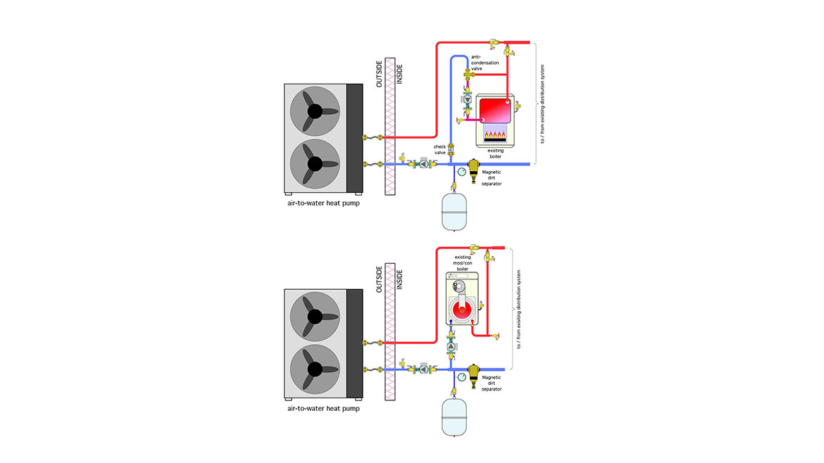
Both heat sources have their own circulator, pressure relief valve, check valves and purging valves. Each circulator operates only when its associated heat source is on, and perhaps for a short time after its heat source is turned off. The latter is a “post purge” function intended to capture residual heat from the mass of the heat source before it dissipates to surroundings.
The valving shown allows either heat source to be isolated and individually purged. It also prevents reverse flow through one heat source when it’s off and the other heat source is on.
Finally, these configurations supply the same inlet water temperature to each heat source. That’s not a big deal for a conventional boiler, but it is for the heat pump. The cooler the inlet water temperature the happier the heat pump.
You’ll see another valve in the piping for the conventional boiler. It’s an anti-condensation mixing valve. Its purpose is to keep the inlet water temperature to the boiler at or above a setpoint — typically about 130° F — whenever possible. It allows the boiler to contribute heat to a distribution system that, at times, may be operating well below the dewpoint temperature of the boiler’s flue gases, but without sustained flue gas condensation. These lower operating temperatures are the result of outdoor reset control of the supply water temperature to the heat emitters. The target temperature for the reset controller should be just high enough to allow the heat emitters to maintain building comfort, based on the current outside conditions. This method of control definitely improves the heat pump’s performance, but it can also destroy an “unprotected” conventional boiler.
Anti-condensation valves use non-electric thermostatic elements that regulate the proportions of entering hot and cool water. It’s also possible to protect a conventional boiler from sustained flue gas condensation using an electronically controlled mixing valve, or a variable-speed circulator. However you choose to do it, be sure to include some reliable method of anti-condensation protection for any conventional boiler as part of your heat pump makeover.
Where to?
The headers to which the heat pump and boiler connect can go to different balance-of-system components depending on the capabilities of the heat sources, and the zoning of the distribution system.
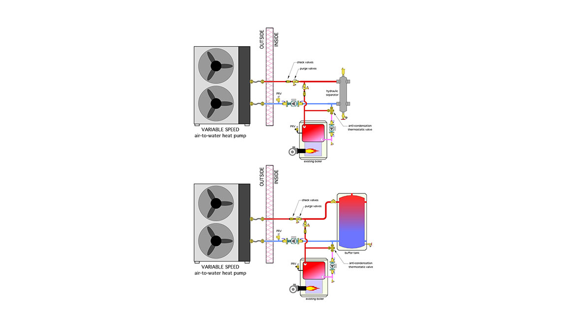
The most common practice to date has been to route the headers to a buffer tank. This is essential if the heat pump has an on/off rather than a variable-speed compressor. It’s also a good practice when the distribution system is extensively zoned. The goal is to prevent either heat source from short cycling. In most cases, a temperature controller operates the heat pump or boiler to maintain some target temperature within the buffer tank whenever the system is in heating mode.
When the heat pump and boiler are both modulating devices, the buffer tank may not be necessary. A hydraulic separator can provide the interface between the heat sources and the distribution system. That separator allows for different flow rates between the active heat source(s), and the distribution system. It also handles air, dirt and magnetic particle separation for the system. An exception to this approach is a system with “micro-zoning,” such as when every panel radiator in the system is independently controlled by a thermostatic radiator valve. In those applications, a buffer tank is still necessary.
Figure 2 shows the piping using either a buffer tank or hydraulic separator.
FIGURE 2
Minimally invasive
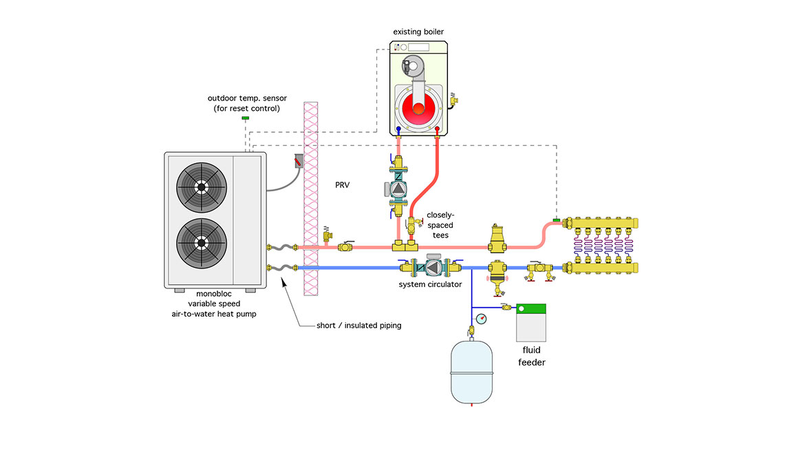
Although parallel piping provides all the right design attributes, there are situations where morphing an existing system into a parallel piping layout would require a lot of repiping. Figure 3 shows an alternative that I’ll call “upstream/downstream” piping. It can often reduce repiping requirements.
FIGURE 3
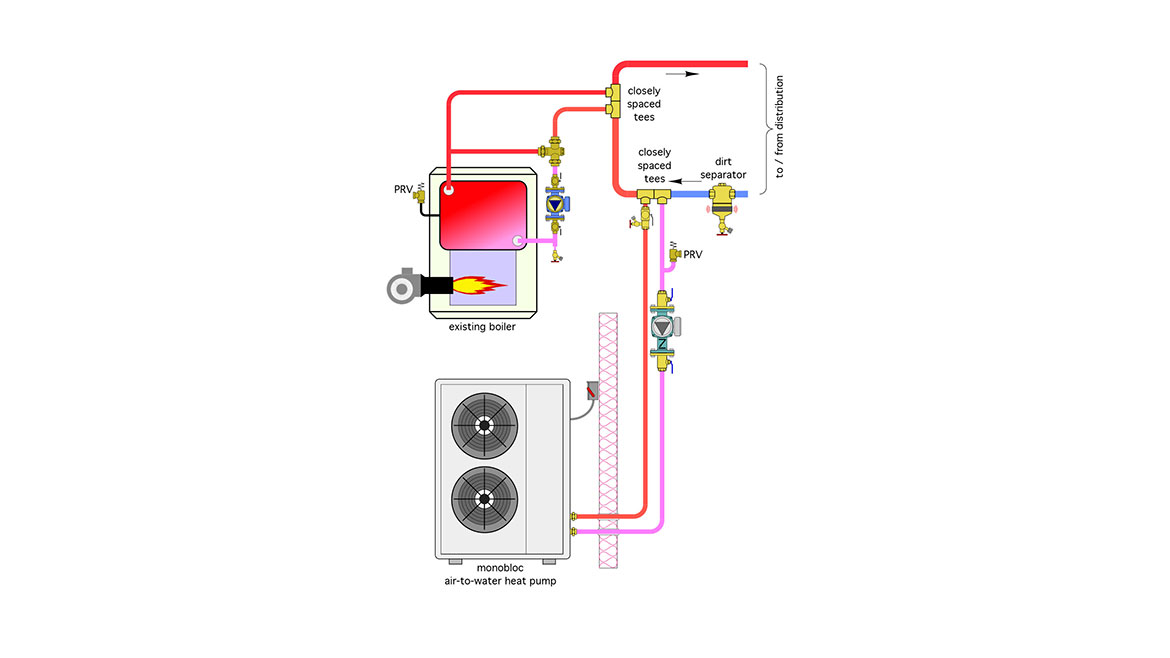
In this approach, the heat pump and boiler are tied into the existing distribution headers using two pairs of closely spaced tees. This allows either the heat source to be online or offline, based on the status of its circulator.
It is very important to connect the heat pump upstream of the boiler. This allows the heat pump to receive the lowest return water temperature to maintain good COP.
If the boiler is operating simultaneously with the heat pump it receives water at temperatures higher than those returning from the distribution system. This will have minimal effect on the efficiency of a conventional boiler, but it will lower the efficiency of a mod/con boiler. Still, considering that the boiler typically only serves as supplemental and backup to the heat pump, the saving in repiping costs may be worth a slight drop in efficiency.
Direct-to-load
As air-to-water heat pump technology — and compressor speed control in particular — continue to be refined, look for systems that eliminate the need for a buffer tank or hydraulic separator. These systems are called “direct-to-load.” The circulator that creates flow through the heat pump also creates flow through the distribution system. When a boiler is needed it’s connected downstream of the heat pump, usually with a pair of closely spaced tees. Figure 4a shows an example.
FIGURE 4a
In this arrangement, flow passes through the heat pump whenever the distribution system is operating. It would also pass through the heat pump if it were down for service and only the boiler was supplying heat. The heat pump varies its compressor speed to maintain the target supply water temperature based on outdoor reset. It also provides a 0-10 VDC signal to the mod/con boiler to regulate its firing rate when operating for supplemental or backup heat.
One could argue that this piping arrangement is not “ideal” from the standpoint of heat loss through the heat pump and its exterior piping, but it’s simple and appropriate when the following conditions are met:
- There is very little piping length between the monobloc heat pump and heated space, and that pipe is well insulated.
- The heat pump uses a variable-speed compressor and operates based on outdoor reset control. This tends to keep the heat pump operating at partial output with flow passing through it most of the time. Outdoor reset also tends to keep the temperature of the fluid passing through the heat pump as low as possible, which reduces heat loss.
- The refrigerant-to-water heat exchanger within the heat pump is insulated.
- The heat pump can be serviced without disconnecting its piping
One desirable aspect of flow passing through the heat pump, even when its compressor is not operating, is freeze protection. If these assumptions are not met, one alternative is shown in Figure 4b.
FIGURE 4b
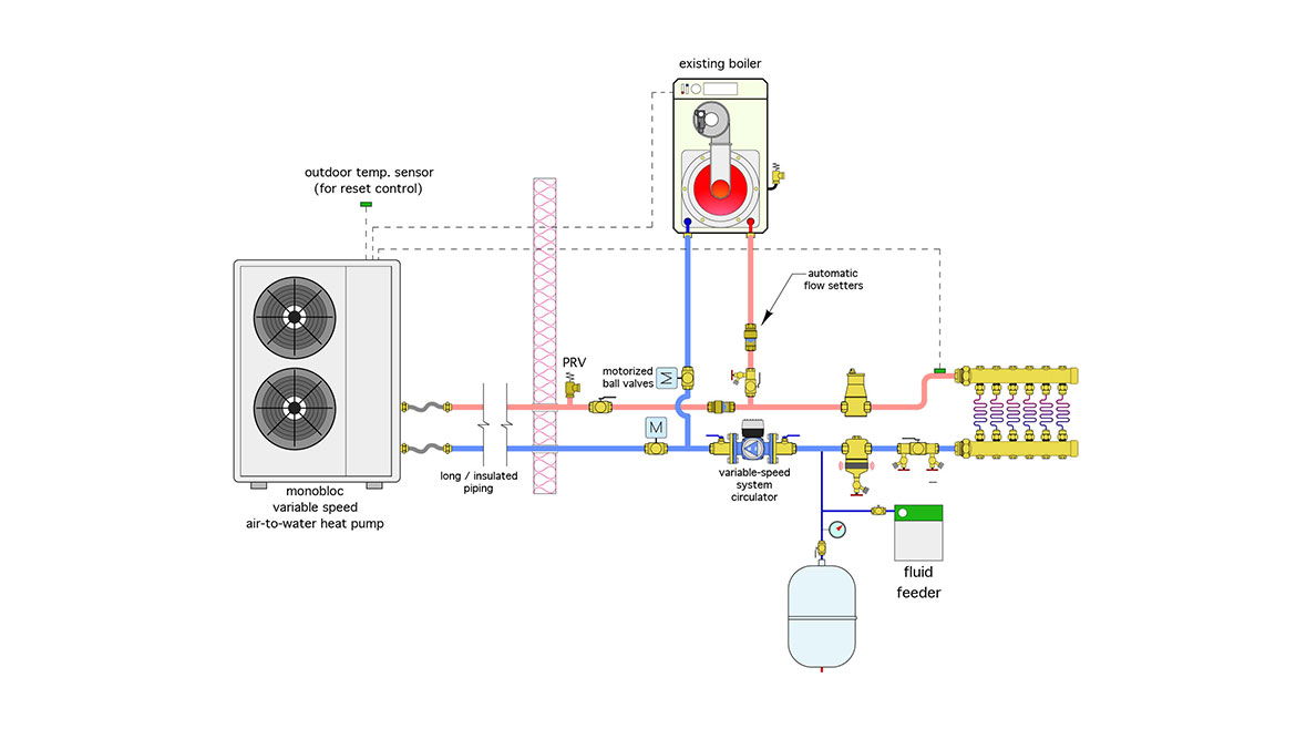
This arrangement allows the heat pump to be isolated from the remainder of the system if it’s off and the boiler is providing all heat input to the system. A single variable-speed circulator set for constant ∆P provides flow for the entire system. The heat sources are in parallel, so they each receive the same inlet water temperature when operating simultaneously. Each heat source subassembly has a motorized ball valve and automatic flow setter. The ball valves open when their associated heat source is on. The automatic flow setters maintain a preset flow rate through each heat source when it’s operating. The heat pump varies its compressor speed to maintain the target supply water temperature based on outdoor reset. It also provides a 0-10 VDC signal to the boiler to regulate its firing rate. Air and dirt separation are provided. The fluid feeder maintains system operating pressure.
Easy scenario
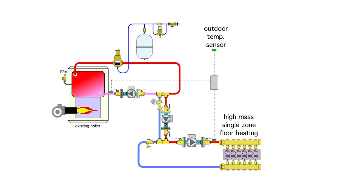
Figure 5 shows an existing system in which a conventional boiler supplies low-temperature radiant panel heating, using a variable-speed circulator for injection mixing. In North America, there are thousands of existing systems that have this or a similar configuration.
FIGURE 5
A split system air-to-water heat pump is an easy tie-in, as shown in Figure 6. Just add a pair of tees, a circulator and — if you like to sleep better at night — a magnetic dirt separator. The latter minimizes the potential for any existing crude in the system to coat the heat pump’s refrigerant-to-water heat exchanger.
FIGURE 6
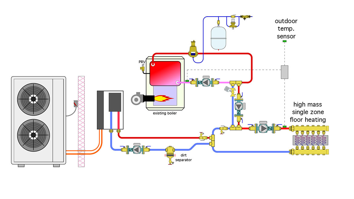
The injection mixing controller takes care of protecting the boiler against flue gas condensation. It does so be slowing the injection circulator when necessary to boost the boiler’s inlet temperature. This eliminates the need for an anti-condensation valve.
A variation on this system would be use of a monobloc rather than split system heat pump. This doesn’t change the piping, but it does change the fluid to a mix of propylene glycol and water. Most manufacturers of monobloc air-to-water heat pumps require the use of antifreeze to protect the heat pump, not only from a potential winter freeze, but also from chilled water cooling conditions that could allow ice to form in the heat pump’s evaporator.
Respecting limits
Most current generation air-to-water heat pumps can comfortably operate with leaving water temperatures up to 130° F. Some can go higher but with a steep reduction in COP. If the distribution system requires higher water temperatures at times, it’s important to sense the water temperature that is, (or could be) entering the heat pump, and turn the heat pump off if that temperature exceeds the manufacturer’s limit for entering water temperature.
One scenario where this is likely is a system in which a boiler supplies a standard indirect water heater. Most indirect water heaters were intended to operate at relatively high coil inlet temperatures in the range of 180° F. That’s well above what most current generation air-to-water heat pumps can provide. If the heat pump is configured to supply such as tank, the coil inside the tank will not be able to accept heat at the same rate the heat pump is delivering heat. This will quickly raise the fluid temperature entering the heat pump and likely cause its internal controller to shut if off.
One relatively simple workaround is to only allow the boiler to supply heat when the thermostat in the indirect water heater calls for heat. Another possibility is to replace the indirect water heater with one that has a much higher coil surface area and may be capable of accepting the full heat output of the heat pump without requiring the fluid temperature to rise above 130° F. Another option is to use a generously-sized brazed plate heat exchanger between the heat pump and a water storage tank. That heat exchanger must be sized to allow the full output of the heat pump to pass into the domestic water without forcing the heat pump’s leaving fluid temperature over 130° F.
Tool up
The inquiries about adding heat pumps to existing hydronic systems will keep coming, and the pace will increase as the target dates for additional electrification get closer. Be prepared with products and piping strategies that respect both the heat pump and the boiler.
Looking for a reprint of this article?
From high-res PDFs to custom plaques, order your copy today!


