search
cart
facebook instagram twitter linkedin youtube
  • Sign In
  • Create Account
  • Sign Out
  • My Account
  • NEWS
  • PRODUCTS
    • FEATURED PRODUCTS
  • CONTRACTORS
    • BATH & KITCHEN PRO
    • BUSINESS MANAGEMENT
    • HIGH EFFICIENCY HOMES
    • TECHNOLOGY
    • WATER TREATMENT
    • PMC COLUMNS
      • Dave Yates: Contractor’s Corner
      • John Siegenthaler: Hydronics Workshop
      • Kenny Chapman: The Blue Collar Coach
      • Matt Michel: Service Plumbing Pros
      • Scott Secor: Heating Perceptions
  • ENGINEERS
    • CONTINUING EDUCATION
    • DECARBONIZATION | ELECTRIFICATION
    • FIRE PROTECTION
    • GEOTHERMAL | SOLAR THERMAL
    • PIPING | PLUMBING | PVF
    • PME COLUMNS
      • Christoph Lohr: Strategic Plumbing Insights
      • David Dexter: Plumbing Talking Points
      • James Dipping: Engineer Viewpoints
      • John Seigenthaler: Renewable Heating Design
      • Lowell Manalo: Plumbing Essentials
      • Misty Guard: Guard on Compliance
  • RADIANT & HYDRONICS
    • RADIANT COMFORT REPORT
    • THE GLITCH & THE FIX
  • INSIGHTS
    • CODES
    • GREEN PLUMBING & MECHANICAL
    • PROJECT PROFILES
    • COLUMNS
      • Codes Corner
      • Natalie Forster: Editorial Opinion
      • Guest Editorial
  • MEDIA
    • EBOOKS
    • PODCASTS
    • VIDEOS
    • WEBINARS
  • RESOURCES
    • INDUSTRY CALENDAR
    • DIRECTORIES
    • PM BOOKSTORE
    • CE CENTER
    • MARKET RESEARCH
    • CLASSIFIEDS
  • EMAGAZINE
    • EMAGAZINE
    • ARCHIVE ISSUES
    • CONTACT
    • ADVERTISE
    • PME EMAGAZINE ARCHIVES
  • SIGN UP!
Radiant & HydronicsThe Glitch & The Fix

Radiant + hydro-air zone

By John Siegenthaler, P.E.
October 31, 2012

Click to enlarge


The Glitch

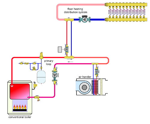
An installer is asked to build a system to supply both radiant floor heating and a “hydro-air” zone. All heat will be supplied from a gas-fired cast-iron boiler. The installer decides to use variable-speed injection mixing to reduce the supply water temperature to the radiant floor portion of the system and operate the radiant floor distribution pump continually to help even out floor temperatures. 

The schematic to the right shows how the system was installed. Can you spot a few problems in the making?


Click to enlarge

The Fix

There are several problems with this layout:

1. The coil within the air handler is not piped for counterflow heat exchange - where the two fluids exchanging heat move in opposite directions through the heat exchanger. This will reduce the rate of heat transfer from the coil.

2. There is no thermal trap in the injection riser piping. This, in combination with continuous circulation in the floor heating subsystem, will create heat migration from the primary loop into the radiant floor distribution system when no heat input is needed by the latter, but hot water is flowing through the primary loop to supply the air handler.

3. There is no balance valve in the injection riser piping. This will likely cause a poor “rangeability” of the injection pump because of the low flow and head requirements it operates with.

4.There is no provision for purging the radiant floor distribution system. The closely spaced tees connecting the injection risers to both the primary loop and the radiant floor distribution system will make it very hard to induce a proper purging flow in the latter.

5. Because it’s installed “downstream” from the other load, the supply water temperature to the air handler will vary depending on the operating status of the injection pump. Since there is no mixing device supplying the air handler, this will cause variations in both heat delivery rate and supply air temperature. If a series primary loop is used, the air handler should instead be the “upstream” load and the radiant floor distribution system, with its mixing assembly, should be the downstream load.

6. There are no purging valves in the return injection riser or the return riser from the air handler. It’s going to take a long time to get the air out.

7. The primary loop circulator is pumping toward (rather than away from) the point where the expansion tank connects to the system. This causes the pressure in the primary loop to drop when the primary circulator is operating. This further exasperates air removal from the system.

8. There are no isolation valves around the circulator in the radiant heating distribution system.

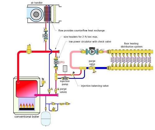
A better way to pipe these loads is shown on the left.

Rather than a primary loop, this system uses “short and fat” headers that are sized for a maximum flow velocity of 2 ft. per second. This, in combination with the inherently low flow resistance of a cast-iron boiler, provides good hydraulic separation between the two circulators connected to the headers. It also allows the same supply water temperature to each circuit connected across the headers. 

The circulator labeled (P1) is necessary to create a second mixing point to boost the boiler inlet temperature and prevent the boiler from operating with sustained flue gas condensation. Depending on the load, this circulator can be relatively small because it has a very low head requirement.

The variable-speed injection pump is shown on the return injection riser. It works just fine in this location and operates at a lower fluid temperature compared to what it would experience if installed in the supply injetion riser. Lower fluid temperatures are less stressful to circulators and will likely result in longer life.

A balancing valve has been installed in the supply injection riser to ensure the injection pump can operate over a wide speed range (and thus with good rangeability).

Purge valves and isolation valves also have been installed where needed.

Finally, the piping connections to the air handler now allow for counterflow heat exchange.


Links

  • The Glitch & The Fix, October 2012
KEYWORDS: hydronic system design incorrect design radiant system design schematic layout

Share This Story

Looking for a reprint of this article?
From high-res PDFs to custom plaques, order your copy today!

John siegenthaler 200x200

John Siegenthaler, P.E., is a consulting engineer and principal of Appropriate Designs in Holland Patent, New York. In partnership with HeatSpring, he has developed several online courses that provide in-depth, design-level training in modern hydronics systems, air-to-water heat pumps and biomass boiler systems. Additional information and resources for hydronic system design are available on Siegenthaler’s website,  www.hydronicpros.com.

Recommended Content

JOIN TODAY
to unlock your recommendations.

Already have an account? Sign In

  • 2025 Next Gen ALL-STARS hero 1440

    2025 Next Gen All Stars: Top 20 Under 40 Plumbing Professionals

    This year’s group of NextGen All-Stars is full of young...
    Plumbing & Mechanical Contractor
    By: Kristen R. Bayles
  • Worker using the Milwaukee Tool SWITCH PACK drain cleaner

    Pipeline profits: Drain cleaning, pipe inspection create opportunities

    Drain cleaning and inspection services offer lucrative...
    Green Plumbing and Mechanical
    By: Nicole Krawcke
  • Uponor employee, Arturo Moreno

    The reinvestment in American manufacturing and training

    Plumbing & Mechanical Chief Editor Nicole Krawcke and...
    Plumbing News
    By: Nicole Krawcke and Natalie Forster
Manage My Account
  • eNewsletters
  • Online Registration
  • Subscription Customer Service
  • eMagazine
  • Manage My Preferences

More Videos

Popular Stories

Hot water pipes

Campus shutdown at Oakland University exposes hidden risks of aging hot-water infrastructure

Floor heating manifold cabinet with flowmeter and PEX pipe.

Elegance extended: How to use the homerun system of connecting heat emitters

Industrial pressure gauge on a tank.

From cutting edge to classic: How to modernize outdated pneumatic control systems

Poll

Will business be up or down in 2025?

Do you anticipate business in 2025 to be up or down in comparison to 2024?
View Results Poll Archive

Products

The Water Came To A Stop

The Water Came To A Stop

See More Products
eBook | 2025 Radiant & Hydronics All Stars

Related Articles

  • Figure 1 Glitch drawing for March The Glitch & The Fix column.

    OK - At a glance: three zone radiant floor heating system

    See More
  • Multiple heating zones for hydronic and radiant applications

    See More
  • Radiant floor heating with pellet boiler

    See More

Related Products

See More Products
  • 51CHeeKvw4L._SX322_BO1,204,203,200_.jpg

    Hydronic Radiant Heating: A Practical Guide for the Nonengineer Installer

  • Classic Hydronics - How To Get The Most From Those Older Hot-Water Heating Systems

  • what hydronics taught holohan.jpg

    What Hydronics Taught Holohan: A Memoir of Life in the Heating Industry

See More Products

Events

View AllSubmit An Event
  • May 29, 2014

    Coffee with Caleffi and John Siegenthaler: Air Source and Water Source Heat Pump Systems.

    Coffee with Caleffi will be hosted by John Siegenthaler on May 29, 2014.
View AllSubmit An Event
×

Keep your content unclogged with our newsletters!

Stay in the know on the latest plumbing & piping industry trends.

JOIN TODAY!
  • RESOURCES
    • Advertise
    • Contact Us
    • Directories
    • Store
    • Want More
    • Supply House Times
  • SIGN UP TODAY
    • Create Account
    • eMagazine
    • eNewsletter
    • Customer Service
    • Manage Preferences
  • SERVICES
    • Marketing Services
    • Reprints
    • Market Research
    • List Rental
    • Survey/Respondent Access
  • STAY CONNECTED
    • LinkedIn
    • Facebook
    • Instagram
    • YouTube
    • X (Twitter)
  • PRIVACY
    • PRIVACY POLICY
    • TERMS & CONDITIONS
    • DO NOT SELL MY PERSONAL INFORMATION
    • PRIVACY REQUEST
    • ACCESSIBILITY

Copyright ©2025. All Rights Reserved BNP Media.

Design, CMS, Hosting & Web Development :: ePublishing