Iron meets microprocessor
The Glitch
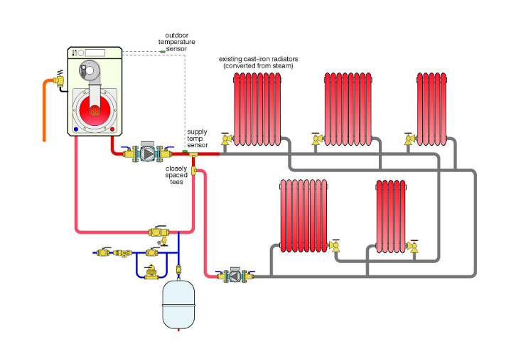
An old New England farm house has been heated with a two-pipe steam system serving plenty of sturdy cast-iron radiators. As part of an extensive renovation and insulation upgrade, the owner decides to upgrade the heat and convert the system to a high-efficiency, gas-fired condensing boiler.
|
| Click to enlarge |
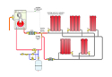
The owner is also complaining about the inability to adjust heat in different rooms. The piping system installed by the local plumber is shown below. It leaves as much of the two-pipe distribution in place as possible.
What are some design details that you think are incorrect or missing?
The Fix
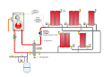
Over decades of use, lots of “crud” can build up in a steam heating system with cast-iron radiators. It’s really a shame to push that crud into new portions of the system and especially into the compact heat exchanger of the new boiler. I’d recommend a hydraulic separator as an ideal way to connect the old iron portion of the system with the new components. It provides hydraulic separation between the boiler circulator and the variable-speed, pressure-regulated distribution circulator. It also provides high performance air separation and dirt separation.
|
| Click to enlarge |
The latter function is enhanced by placing the hydraulic separator as low as possible within the system. Be sure to leave room for a blow-down valve at the bottom because you are sure to be using it. Also be sure the flow velocity into the hydraulic separator is not more than 4 ft. per second.
The fix drawing also shows the use of wireless thermostatic radiator valves, rather than manually operated globe valves, at the inlet of each radiator. This effectively converts each radiator into its own zone and allows the owner to adjust the temperatures in different areas of the house as he wants. These valves are a perfect complement to the variable-speed, pressure-regulated circulator.
Other details that are incorrect in the original drawing include:
- The circulator in the boiler loop should be pumping into the condensing boiler (because the latter has a high flow-resistance heat exchanger).
- If you expect hydraulic separation between circuits, do not install closely spaced tees as shown in the Glitch drawing. Instead, provide a minimum of 6” pipe diameter of straight pipe both upstream and downstream of the closely spaced tees.
- There is no microbubble air separator in the system.
- The supply temperature sensor for the boiler should be downstream of the point of hydraulic separation between the boiler circuit and distribution circuit. This allows the boiler to react to any mixing taking place.
- The purging valve should be upstream of the makeup water connection.
- One circulator is at the low point of the distribution system - the most probable location for sediment to collect.
- There is no way to purge air from individual radiators.
- There is no effective way to purge the distribution circuit.
Links
Looking for a reprint of this article?
From high-res PDFs to custom plaques, order your copy today!


