John Siegenthaler: Modern biomass meets state-of-the-art hydronics
This wood-pellet system example is intended to supply space heating and domestic hot water.
There will always be fringe markets for products that use renewable energy to provide marginal heating comfort. These markets survive because early adopters willingly sacrifice superior comfort as the perceived price for using renewable energy.
However, I contend that renewable-energy heating systems will only gain mainstream acceptance if they provide comfort that’s as good — if not better — than conventional systems. The typical North American consumer will not knowingly sacrifice comfort just to shift the source of their heating energy from conventional to renewable energy sources.
I also maintain that widespread use of renewable-energy-based systems requires they be economically sustainable without government subsidies and serviceable by any reasonably competent HVAC technician.
Time and again, our industry has witnessed attempts at developing central heating solutions based on renewable energy that did not meet one or more of these conditions. Many of these attempts failed to generate a sustainable solution that would be as likely to be used in a typical suburban home as it would be to stir the passions of carbon minimalists.
There is no silver-bullet solution to these requisite issues of comfort, affordability and reliability. Instead, there are constant refinements of the techniques and hardware we use. The industry must keep striving for solutions that are:
- Sophisticated but simple;
- Renewable yet reliable;
- Ecologically sound and economically sustainable; and
- Refined as well as repeatable.
Polishing Pellet Performance
Over the last few years, I’ve worked on many projects involving wood-pellet boilers. I’ve seen very successful applications as well as a situation where the owner eventually just gave up and told whoever was responsible to “get that thing out of my basement.” Many lessons learned have led to significant improvements and progress toward designs that meet all the bullet points listed above.
This month, I’m presenting a concept for a system that embodies many simple but salient details based on these experiences. This system is intended to supply space heating and domestic hot water to residential or light commercial buildings using a pellet boiler as the renewable energy heat source, and radiant panels as the comfort delivery method.
It makes use of contemporary hydronics technology such as variable-speed circulators, stratified thermal storage, hydraulic separation, injection mixing and on-demand domestic water heating. It creates conditions that complement rather than compromise the desirable operating characteristics of the pellet boiler — and those of the balance-of-system components.
Figure 1.
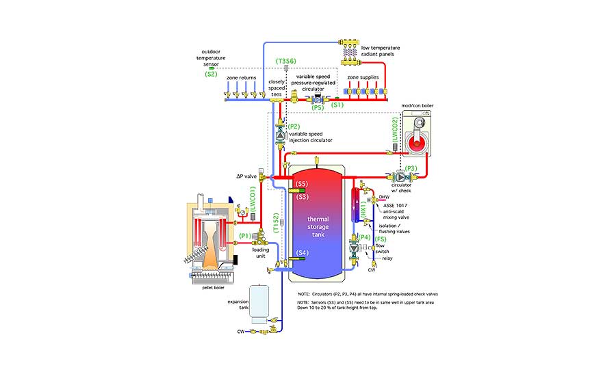
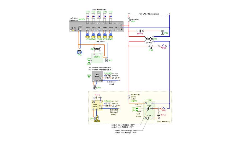
A piping schematic for the system is shown in Figure 1. An electrical control diagram is shown in Figure 2.
These schematics should be considered as starting points from which a final system design can be developed. Although they show the majority of the required hardware, designers using them are still responsible for adding specific safety or code-required devices as well as for the proper sizing of all piping, circulators and more.
Radiant Comfort
This system assumes the use of radiant panels that can provide design load output using a supply-water temperatures of 120° F or less. The distribution system has multiple zones, each controlled by a standard zone valve.
A variable-speed pressure-regulated circulator (P5), operating in constant differential pressure mode, provides consistent flow through each zone regardless which zones are operating. The fewer the number of active zone circuits, the lower the power demand of circulator (P5). That’s state-of-the-art “cruise control” for distribution system flow rate along with significant electrical energy savings.
The primary heat source is a modern wood pellet boiler. It’s combined with a thermal storage tank having a nominal 2 gallons of volume per 1,000 Btu/h of pellet boiler capacity. This tank lets the pellet boiler operate with long on-cycles followed by long off-cycles, which allows the boiler to achieve high thermal efficiency with minimal emissions.
Figure 2.
A suggested operating scenario is one that provides an average run cycle length of three hours per start. Modern pellet boilers internally log both run time and number of starts so that the boiler’s performance can be verified.
The pellet boiler operates completely independent of calls for heat from zone thermostats.
This is obviously different from what the hydronic heating industry is used to. To achieve long on-cycles, the pellet boiler is turned on and off based on the temperatures at two sensors in the thermal storage tank. A single controller (T152) monitors both sensors and allows independent open/close settings for each of its two relay outputs.
The pellet boiler is turned on when the upper tank sensor (S3) detects a temperature of 128° or less. The boiler continues to fire until the lower tank sensor (S4) reaches 175°. This operating logic provides a wide swing in tank temperature during each boiler cycle. Wide temperature swings in thermal storage encourage those desired long on-cycles. These temperature set points also maintain the upper portion of the thermal storage tank hot enough to supply domestic hot water whenever it’s needed.
Heat transfer from thermal storage to the distribution system is regulated by a variable speed injection circulator (P2) with a standard PSC (permanent split capacitor) motor. Heat input varies based on keeping the supply water temperature at sensor (S1) at or very close to a “target” temperature that’s continuously calculated by outdoor reset control logic. Circulator speed control and outdoor reset logic are provided by the (T356) controller.
It would also be possible to use an ECM circulator for (P2) provided it was controlled based on outdoor reset logic.
This system also uses a differential pressure bypass valve (∆P valve) set for 1.5 psi to prevent flow through the pellet boiler when it and its associated circulator (P1) are off. This is important since pellet boilers do not use motorized flue dampers to limit off-cycle convective losses up the chimney. The ∆P valve prevents reverse thermosiphoning from the thermal storage tank through the boiler and associated piping. It replaces the need for a check valve between the pellet boiler and thermal storage tank.
The pellet boiler is protected against sustained flue-gas condensation by a loading unit, which combines a circulator with a thermostatic mixing valve. That valve’s cold port is completely closed when the boiler starts from room temperature. This prevents heated water from flowing to the load or thermal storage tank. Instead, the heated water remains in the boiler loop to bring the boiler’s heat exchanger above the dew point temperature of the flue gases as quickly as possible. As the water temperature from the loading unit to the pellet boiler climbs above 130° the cold port of the valve begins to open while the bypass port (at the top of loading unit) begins to close. The cold port will be fully open and the bypass port completely closed when the water temperature leaving the loading unit reaches 148° or higher.
Peaking Power
The pellet boiler, if operating as described above, could provide year-round heat for both space heating and domestic hot water generation. However, just like any boiler, it could also be down for service when heat is needed, or it could be intentionally turned off during warmer weather.
It’s also possible that the pellet boiler would not be sized for the full design heating load. Although that might seem heretical to most boiler specifiers, it’s an acceptable and sometimes required practice with pellet boilers. Undersizing relative to design-load keeps the boiler operating with long on-cycles for high efficiency and low emissions.
Boilers that are undersized relative to design load should, in theory, operate essentially 100% of the time during design-load conditions. The only time an undersized pellet boiler should turn off under design load conditions is for automatic cleaning cycles, which typically occur every four to six hours and only last a few minutes.
Interestingly, a pellet boiler sized for 75% of a building’s design heating load in a typical upstate New York climate would still supply about 96% of that building’s seasonal space heating energy requirement. That probably sounds implausible, but it’s based on an analysis of bin temperature data. Simply put, most boilers spend the vast majority of their operating hours at partial load conditions that are significantly lower than design load.
This system uses a mod/con boiler, likely fueled by propane in rural locations, to cover times when the load is greater than 75% of design conditions. That boiler is piped across the upper portion of the thermal storage tank. This allows it to “exercise” the thermal mass in the upper 10-20% of the tank as a deterrent against short cycling.
Temperature stratification in combination with the tank piping shown limits the amount of tank water the auxiliary boiler interacts with. Auxiliary boiler buffering is very important when the distribution system is divided into many zones, some of which may have heating requirements well below the mod/con boiler’s minimum modulation rate. An example would be a small towel-warming radiator operating in the master bathroom on a cool fall morning.
Under normal operating conditions, the pellet boiler should maintain a temperature no lower than 128°-130° at the top of the thermal storage tank. However, if it can’t, the mod/con boiler comes to the rescue when the upper tank temperature drops to 125° or below. Maintaining the hot-water reserve at the top of the tank is critical for the on-demand domestic water-heating subsystem as well as expedient delivery of heat to space heating zones.
As Needed
Domestic hot water is provided on demand by combining the hot-water reserve at the top of the thermal storage tank with a stainless steel heat exchanger mounted outside that tank.
Having the heat exchanger outside the tank allows full servicing or even replacement, if necessary. This is not possible with most indirect water heaters using internal coil heat exchangers.
An external heat exchanger can also be sized to fully heat cold domestic water to its final delivery temperature when the water temperature at the top of the thermal storage tank is only about 5°-10° to higher than that delivery temperature. This allows the mod/con boiler to operate within its condensing range while providing domestic water heating.
A flow switch (FS) in the cold domestic water piping closes whenever the building’s demand for domestic hot water exceeds 0.6 gpm. This turns on circulator (P4) via a relay. Hot water from the top of the thermal storage tank immediately flows through the primary side of the stainless steel heat exchanger (HX1) as cold domestic water flows through the other side.
The temperature response time of a brazed-plate heat exchanger is very fast due to its high internal surface-area-to-volume ratio. Fully heated domestic water should be available from the outlet of the heat exchanger within 3 to 4 seconds after the flow switch closes. The stainless steel brazed-plate heat exchanger should be sized to fully heat the domestic water to a minimum 115° delivery temperature based on 125° water available from the top of the tank.
Given the temperature control logic used by the pellet boiler, there will be times when the water temperature in the upper portion of the tank is well above 125°. It could be as high as 190°. Because of this, it’s crucial to provide an ASSE 1017-rated anti-scald valve between the outlet of the domestic water heat exchanger (HX1) and the hot-water plumbing system.
Combination isolation/flushing valves are provided so the domestic water side of the brazed-plate heat exchangers can be acid washed to clean away scale accumulation. The DHW subsystem also includes a pressure relief valve on the heat exchanger side of the isolation/flushing valves.
When the faucet is turned off, this on-demand approach to domestic water heating leaves very little hot domestic water in the system relative to tank-type heaters. That decreases standby heat loss. It also reduces the potential for Legionella bacteria colonization.
Heat migration from the thermal storage tank is minimized by a differential pressure bypass valve between the tank and pellet boiler, a spring check valve inside circulator (P2), and a spring check valve in the auxiliary boiler piping.
Write It Down
When you’re planning a system like this, one that’s not a routine installation, it’s essential to create a description of operation. An example of such a description for the system shown in Figures 1 and 2.
You Take It From Here
We’ve discussed a renewable energy heating system with a lot of synergistic attributes. Many of those attributes are made possible by the versatility of modern hydronics technology.
I’ll leave it to PM readers to finalize these concepts for their own system needs and, in doing so, push the envelope on “sustainable” use of renewable thermal energy a bit further.
Sample System Description Of Operation
Power Supply: 120 VAC power for the pellet boiler is supplied from a dedicated circuit. The service switch for the pellet boiler must be closed, and the low-water cutoff (LWCO1) must detect water for the pellet boiler to operate.
120 VAC power for the auxiliary boiler is supplied from a dedicated circuit. The service switch for the auxiliary boiler must be closed and the low water cutoff (LWCO2) must detect water for the auxiliary boiler to operate.
Power for the circulators (P2) (P4) and (P5), the 24 VAC transformer (X1), the multi-zone relay center (MZRC), temperature controller (T152), and relay coil (R2) is supplied through another 120 VAC dedicated circuit. The main switch (MS) must be closed for these devices to operate.
Pellet boiler operation: The pellet boiler enable switch (PBES) must be closed for the pellet boiler to operate. Whenever sensor (S3) in the upper portion of the thermal storage tanks is below 128° the stage 1 contacts in the (T152) controller close. This passes 24 VAC from transformer (X1) to relay coil (R2).
Relay contact (R2-1) closes across the external demand terminal of the pellet boiler. The pellet boiler turns on circulator (P1) and initiates its startup routine. Relay contact (R2-2) also closes. 24 VAC passes through the closed stage 2 contacts of controller (T152) and through the closed contacts (R2-2) to provide another path for 24 VAC to relay coil (R2).
When the temperature at the upper tank sensor (S3) reaches 132°, the stage 1 contacts in the outdoor reset controller (T152) open. However, 24 VAC continues to pass through the closed stage 2 contacts in controller (T152) and closed contacts (R2-2) until the lower tank sensor (S4) reaches 175°. At that point, the stage 2 contact in controller (T152) opens, breaking 24VAC to relay coil (R2), which removes the external demand from the pellet boiler, allowing it to follow its normal shut-down procedure.
Auxiliary boiler operation: The internal controller within the auxiliary boiler monitors the temperature at sensor (S5) in the upper portion of the thermal storage tank. If that temperature drops to or below 125°, the auxiliary boiler turns on, along with its associated circulator (P3). Heated water is directed from the auxiliary boiler to the upper left header of the thermal storage tank. From there, it can either flow to the load through circulator (P2) if a heating zone is active, or through the upper portion of the thermal storage tank. When the temperature at sensor (S5) reaches 135°, the auxiliary boiler and circulator (P3) are turned off.
Space heating distribution system operation: Upon a call for heating from any zone thermostat (T1, T2, T3, T4, T5), the associated zone valve (ZV1, ZV2, ZV3, ZV4, ZV5) is turned on the by the multi-zone relay center (MZRC). Circulator (P5) is turned on and operates in a preset constant differential pressure mode. 120 VAC is also passed to transformer (X2), which provides 24 VAC to the (T356) variable-speed injection controller.
The (T356) controller boots up and measures the current outdoor temperature. It uses that temperature along with its settings to calculate a target supply water temperature for the distribution system. The (T356) then controls the speed of circulator (P2) to inject hot water from the upper left header of the thermal storage tank into the distribution system at the closely spaced tees.
The rate of hot water injection varies in an attempt to hold the supply water temperature measured at sensor (S1) as close to the target temperature as possible. This operation continues as long as one or more zones remain active. When all zone thermostats are satisfied, the (MZRC) turns of circulator (P5), transformer (X2), and the injection mixing controller (T356).
Domestic water heating: The temperature of the upper portion of the thermal storage tank is continuously maintained at or above 125° by either the pellet boiler or auxiliary boiler. Whenever there is a demand for domestic hot water of 0.6 gpm or higher, flow switch (FS) closes, passing 24 VAC to the coil of relay (R3). Relay contact (R3-1) closes to turn on circulator (P4), which immediately routes hot water from the top of the thermal storage tank through the primary side of stainless steel heat exchanger (HX1).
Cold domestic water passes in counterflow through the other side of heat exchanger (HX1) and is fully heated to or above the desired domestic hot water delivery temperature of 115°. The hot water leaving (HX1) passes through an ASSE 1017-listed anti-scaled mixing valve to ensure that the maximum hot water delivery temperature to the plumbing system is 115°. When the domestic hot water flow rate drops to 0.4 gpm or less, the flow switch (FS) opens, turning off relay coil (R3) and circulator (P4).
Suggested initial controller settings:
Stage 1 contacts in (T152) controller:
Contacts close at 128°, open at 132°.
Stage 2 contacts in (T152) controller:
Contact close at 165°, open at 175°.
Injection mixing controller (T356) settings:
No load condition: 70° supply water temperature when outdoor temperature is 70°.
Design load condition: 110° supply water temperature when outdoor temperature is 0° or lower.
To read Siegenthaler’s article: “Modern biomass meets state-of-the-art hydronics” in pdf form, please see here.
Looking for a reprint of this article?
From high-res PDFs to custom plaques, order your copy today!


