John Siegenthaler: 5 more products the hydronics industry needs
These products would help fill needs within the hydronics market.
In last month’s Hydronics Workshop column I described five devices that would, in my opinion, improve and expand the North American hydronics industry. Here’s my “wish list” from that column:
- A plug-and-play controller for radiant cooling;
- Interior air-to-water heat pumps;
- A draft regulator that seals against positive pressure;
- Spring-loaded check valves with multiple pressure inserts; and
- Better thermal storage tanks.
After writing that column, it occurred to me: Why stop at five? Think bigger, ask for more than you expect, and see what develops. So here are another five products that I think could further enhance North American hydronics technology.
A vapor-tight insulation system for circulator volutes
If you’ve used cast-iron circulators in any type of chilled water cooling system or in earth loops for geothermal heat pumps, you’ve likely seen what happens to the volute, steel flange bolts, and even steel handles on isolation flange valves when they rack up a few operating hours well below the dewpoint temperature of the surrounding air. All these components quickly develop surface oxidation. Figure 1 shows some examples.
> FIGURE 1 Photo credit: John Siegenthaler
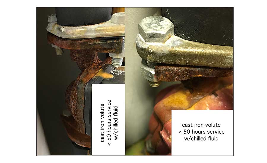
Over time, the orange condensate drips onto anything below it. This “superficial” rust doesn’t compromise the circulator’s performance, but it does make a mess, and certainly doesn’t look very professional to clients. The occurrence of this problem also seems to be brand-agnostic.
The obvious solution is to add a vapor-tight insulation envelope around all parts of the circulator other than the motor can and wiring compartment. That’s easier said than done. The shape of circulator volutes, flanges and isolation valves doesn’t lend itself to off-the-shelf products that can be used by installers who don’t specialize in custom pipe insulation work.
Some manufactures offer molded foam clam shells that fit specific circulators — usually commercial-size ECM products. These can limit condensation — if they are properly sealed at all locations where air could contact any chilled metal surface, including the volute, flanges, flange bolts and adjoining piping.
Breaking the continuity of this insulation/vapor barrier envelope, at any point, sets the stage for condensation. Even worse, the condensation and resulting corrosion of ferrous metal surfaces is often hidden behind the insulation. The condensate can run downward between the piping and insulation, eventually leaking out of unsealed seams or butt joints. It’s also critical not to insulate the motor can or electrical connection box. That implies an air-tight seal is required between the base of the motor can and the insulated portion of the circulator.
Wouldn’t it be nice to have an insulation/vapor barrier system that could fit any circulator that may have to operate at sub-dewpoint temperatures?
Perhaps a block of solid insulation material that could be easily molded on-site to the shape of the installed circulator, and then attached as two mating parts. Maybe a hollow plastic shell that could be fit around the installed circulator volute and flange joints, and then filled with expanding foam.
An elastomeric gasket would be part of either approach to provide the air-tight seal with the circulator’s motor can. The portion of the circulator that contacts the insulation could be sprayed with a “release agent” that prevents strong bonding in case the insulation had to be removed to service or replace the circulator.
A simple, inexpensive temperature controller for variable speed ECM circulators
Over the last 25-plus years I’ve designed many hydronic systems that had one or more circulators with standard PSC motors operated by variable speed controllers. Those controllers used a combination of AC wave chopping and frequency control to vary the speed of the circulator. They have performed well in a variety of applications, including radiant panel heating, snowmelting and boiler anti-condensation protection.
However, the circulator world is quickly changing. Those familiar wet-rotor circulators with PSC motors are about to go the way of 100 watt incandescent light bulbs and R-22 refrigerant. I suspect they will be out of production within the next five years, perhaps even sooner depending on politics. Circulators with high-efficiency ECM motors are quickly becoming the new normal.
Variable speed controllers using wave chopping and frequency control cannot be used with ECM circulators. So, it’s just a matter of time until those controllers follow PSC circulators into the annals of hydronic history.
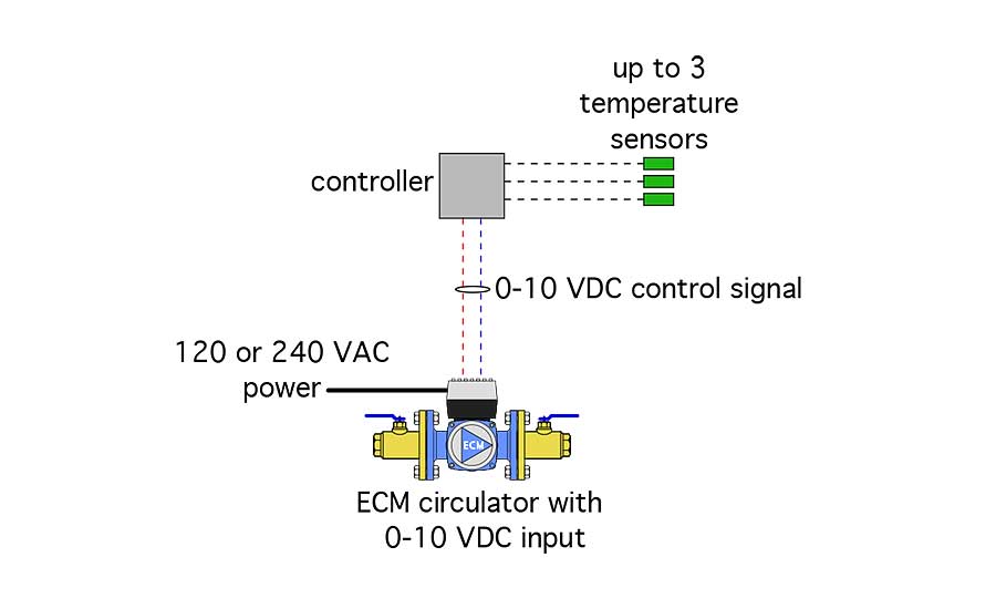
The good news is many of the new ECM circulators can be speed-controlled using a 0-10 VDC input signal (not to be confused with the standard 120 VAC electrical power supply). A typical scenario is for the circulator to remain off until the control signal reaches 2 volts. The circulator’s speed then increases in direct proportion to the control voltage, reaching full speed at 10 volts.
What’s needed are simple and inexpensive controllers that generate a 0-10 VDC output signal in relationship to some temperature-based condition. The latter could be a user-set “target” temperature, with circulator speed selectable as increasing or decreasing as the temperature measured by the controller varies from the target value. This function allows for supply water temperature control as well as boiler anti-condensation protection.
The controller should also handle differential temperature control, such as those used in solar thermal systems or biomass boiler systems. It should also be able to provide variable speed injection mixing based on either a fixed target supply temperature, or a target temperature calculated using outdoor reset logic. All these functions are just selectable code within the controller’s firmware. The controller should have connections for up to three temperature sensors, as shown in Figure 2.
> FIGURE 2
A multi-function controller for biomass boiler systems
There are lots of potential applications for boilers burning wood pellets or chips. These “biomass” boiler systems require several control functions, including boiler anti-condensation protection, boiler firing based on two or more temperatures within a thermal storage tank, variable speed injection of heat into a distribution system, differential temperature control to prevent auxiliary heat from entering storage, coordinated operation of an auxiliary boiler and zoning.
All these functions can currently be provided by combining several independent single-function controllers along with an assortment of relays. Figure 3 shows an example of a “multi-box” control schematic for a system having both a pellet boiler and auxiliary boiler.
> FIGURE 3
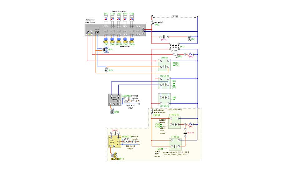
Although these multi-box control systems work, their installation and programming can be very challenging for technicians who may not understand overall system operating requirements. I can attest that this has been a significant barrier to successful biomass boiler installations, especially in residential or light commercial applications. This situation could be greatly improved if the market provided an integrated controller to handle all necessary control functions. The functionality exists, it is just a matter of repackaging it in one box.
Indirect tanks with larger coil heat exchangers
The future of hydronics is low water temperature. Contemporary heat sources, such as geothermal water-to-water heat pumps or air-to-water heat pumps, typically max out at water temperatures ranging from 120° F to 130°. That’s hot enough for many types of heat emitters, such as well-designed radiant panels or panel radiators. It’s also sufficient to create domestic hot water at perhaps 110° to 115° if there’s a suitable heat exchanger between the source water from the heat pump and the domestic water.
Most of the currently available indirect water heaters in the North American market are very limited in such applications. The internal coil heat exchangers in these tanks don’t have sufficient surface area to transfer heat from a much lower temperature heat source to the domestic water at the heat output rate of the source, and at a minimum temperature differential of 5° to 10°. The result will be short-cycling, heat pumps locking out on fault conditions, and complaints about inadequate domestic hot water.
Most North American indirect water heaters were developed assuming that a boiler would be the heat source, supplying water to the internal coil heat exchangers at temperatures of 180° to 200°. Swap out that assumed boiler with a heat pump, and you have a very significant heat transfer “bottleneck.”
One solution is to use an external stainless steel heat exchanger sized for very low approach temperature differences. This works, but it’s arguably more complex than an indirect water heater.
Another solution would be to markedly increase the surface area of the coil heat exchanger inside indirect tanks. Coils with three to five times the surface area of a typical indirect are needed. Such coils would likely span from the bottom to the top of the tank shell as depicted in Figure 4.
> FIGURE 4
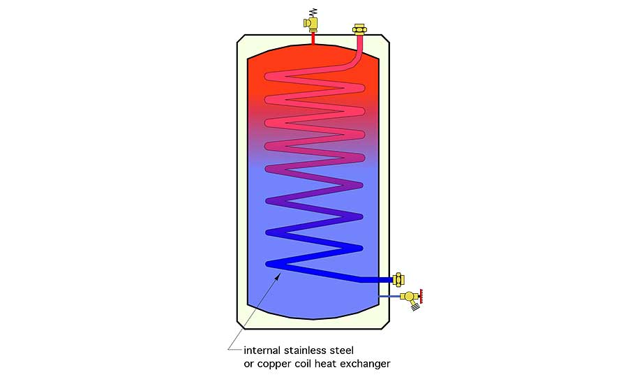
The coils would be made of either stainless steel or copper. The water passing through them could be from the heat source, or it could be domestic water. The later “reverse-indirect” concept allows the tank to provide domestic water as well as buffering for zoned space heating loads. It also allows the pressure vessel to be made of carbon steel, which is much less expensive than stainless steel.
I would also suggest that such tanks have R-24° F•hr•ft2/Btu insulation on all surfaces, and ample ports for a variety of applications. See my “wish list” item No. 5 in last month’s column for more on this.
Peel and stick elastomeric foam pipe insulation that stays together
My last plea is born out of frustration. I’ve had many occasions to see (and fix) peel and stick elastomeric foam pipe insulation with seams that have reopened only a few weeks after installation. The insulation was installed correctly, at reasonable temperatures, and without contaminating the adhesive surfaces. Yet, it reopened. I suspect I’m not the only one who has experienced this problem.
I’ve fixed the problem by using 1.5-inch wide high quality vinyl electrical tape centered along the slit line. This works, but it shouldn’t be necessary. Perhaps the product branding should change from “peel and stick” to “peel, stick and stay.”
Thanks again for tolerating my hydronic hankerings. Perhaps some of these ideas will come to fruition to sustain and advance the North American hydronic market.
To read Siegenthaler’s article: “5 more products the hydronics industry needs” in pdf form, please see here.
Also, see the first “5 products the hydronics industry needs” in pdf form, please see here.
Looking for a reprint of this article?
From high-res PDFs to custom plaques, order your copy today!


