John Siegenthaler: 5 products the hydronics industry needs
These products would help fill needs within the hydronics market.
All companies that supply hydronic heating hardware to the North American market strive to offer products that are currently in demand. Some even look farther down the road, anticipating where the market is headed. They develop strategies for products that may be ahead of their time, yet eventually stand ready to fill a future market niche.
Most of us who have worked in the hydronics industry have ideas for new or improved products that could make our job easier, faster or more profitable — ideas that could move the industry closer to the goal of creating superior comfort where and when it’s needed, using the least amount of energy possible.ll companies that supply hydronic heating hardware to the North American market strive to offer products that are currently in demand. Some even look farther down the road, anticipating where the market is headed. They develop strategies for products that may be ahead of their time, yet eventually stand ready to fill a future market niche.
This month, I’ll ask for your indulgence as I describe five of my “wish list” product ideas. I’ll do my best to justify why I think these products are needed.
A plug-and-play controller for radiant cooling
There are many indications that electrically driven heat pumps will claim an increasing share of the future hydronic-heat-source market. Society’s increasing ambivalence toward fossil fuels, government policies and incentives that encourage low-carbon renewables, and utility scale electricity from wind farms and large photovoltaic installations all help shape this trend.
Geothermal water-to-water heat pumps and air-to-water heat pumps will both see increasing use as hydronic heat sources. The icing on the cake is that both of these heat pumps can also supply chilled water for cooling. The North American hydronics industry needs to get ready to supply simple and repeatable solutions for small scale chilled water cooling.
The current standard approach is to pipe chilled water to one or more air handlers — each equipped with drip pans — and deliver both sensible and latent cooling using forced air. This works, but it also represents significant additional costs in systems that use hydronic radiant panels for heating.
When a radiant panel system is already part of the comfort solution and a heat pump will be used as the heat source, it seems logical to use the same radiant panel for sensible cooling combined with a small air handler for latent cooling and ventilation.
I especially like the use of radiant ceiling panels for both heating and cooling. Ceiling panels eliminate the floor-covering issues that sometimes arise in floor-heating applications. Technically, they are also the ideal surface for radiant cooling.
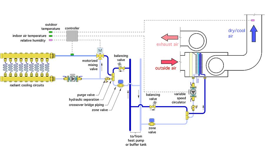
We have all the hardware needed to build hydronic radiant panels. We also have three-way motorized mixing valves to regulate water temperature. What we don’t have is a simple plug-and-play controller that can regulate water temperature to the radiant panels in both heating and cooling modes.
The output of such a controller could be a standard three-wire floating control signal that would control a three-way motorized mixing valve. It might also be a 2-10 VDC or 4-20 mA analog output that could regulate a variable-speed injection circulator.
During cooling mode, the controller would track interior dew point temperature and reliably keep the chilled water supplied to the radiant panel a few degrees above that temperature. It should also be capable of controlling interior relative humidity by regulating chilled water flow through a dehumidifying coil in an air handler. In heating mode, the controller would operate the three-way motorized mixing valve or a variable-speed injection circulator to maintain a set supply water temperature or a temperature based on outdoor reset control. The controller would be supplied with all necessary sensors for temperature and relative humidity, eliminating the need for designers to source separate hardware. Figure 1 on Page 12 shows a possible piping arrangement for the hardware associated with this controller.
> FIGURE 1
Interior air-to-water heat pumps
Over the last few years, I’ve written several PM columns on air-to-water heat pump systems. They have all described heat pumps that are located, in part or in total, outside the buildings they serve. These “monobloc” or “split” system configurations are definitely the most common configuration for air-to-water heat pumps at present, but they are not the only possibility.
At least two European suppliers currently offer air-to-water heat pumps that are located within the building they serve. Outside air is routed into and out of the heat pump’s air handler section through short runs of large-diameter flex duct. An example of one such product is shown in Figure 2.
> FIGURE 2
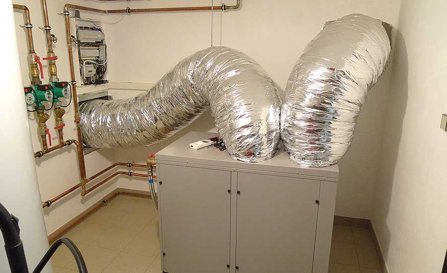
Keeping the heat pump inside allows for features such as domestic water heating (using a desuperheater or a dedicated heat exchanger). It also eliminates the need for antifreeze or isolation heat exchangers in cold-climate applications. And when it comes to service, where would you rather be standing on a cold and windy January night — in a snow drift with a flashlight or in a dry, well-lit mechanical room? North America needs an interior air-to-water heat pump offering complete with outside air intake and discharge hoods, and appropriately sized flexible ducting.
A draft regulator that seals against positive pressure
Over the last several years, I’ve been heavily involved with pellet boilers. Most of these boilers have induced-draft fans capable of creating slight positive pressure in vent connector piping when the chimney draft is less than the exhaust gas flow rate. This tends to happen when a pellet boiler first starts up and vents into a cold masonry chimney.
This situation causes flue gases and small amounts of fly ash to be ejected from the openings in standard barometric dampers that are only designed to prevent excessive negative pressure in the venting system. The barometric dampers cannot seal against temporary positive pressure in the venting system. This can lead to a mess, as evidenced by the barometric damper shown in Figure 3 on Page 16.
> FIGURE 3
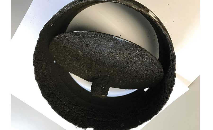
It’s very clear this damper has been through more than simply admitting room air into a vent to control negative draft pressure. The fly ash makes the spillage very evident. However, I’m sure there are oil-fired and gas-fired boilers in service where flue gases, including carbon monoxide, spill from barometric dampers when their associated boiler fires into cold masonry chimneys that initially creates very low draft. Those systems don’t leave as much visual evidence, which is arguably not a good thing. Flue gas spillage from barometric dampers needs to be minimized or, even better, eliminated.
Draft regulators that seal against positive pressure are available from several European suppliers. Figure 4 shows two examples.
> FIGURE 4
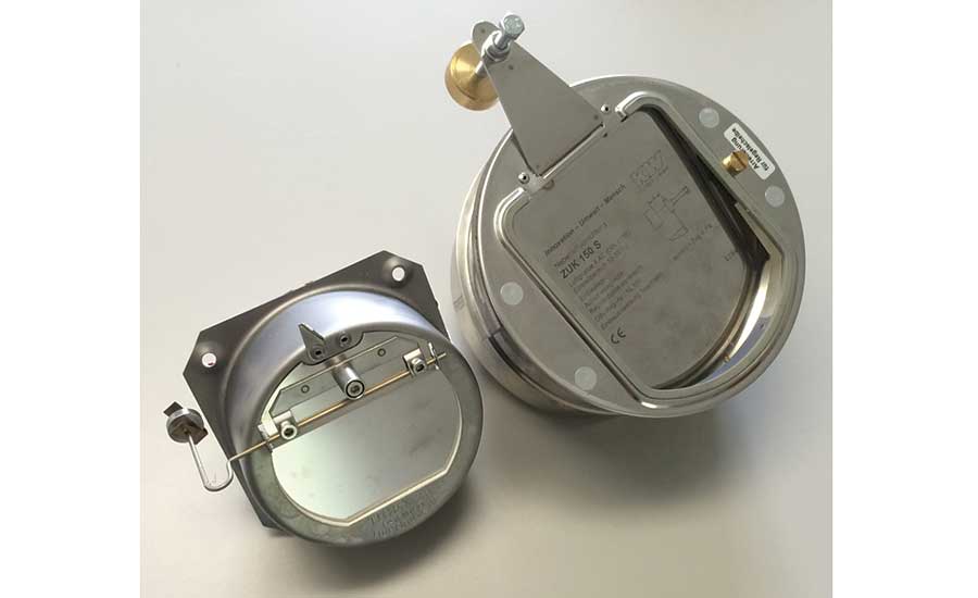
These draft regulators are made of stainless steel and have a gasket around the air inlet opening. The hinged blade closes against this gasket if the pressure inside the vent is higher than outside. I’ve seen one of these products perform well in a biomass boiler application, and while I can’t guarantee that not a single molecule of flue gas could escape from these products, they are a significant improvement over standard North American barometric dampers.
Unfortunately, neither of these products is currently UL-listed, and without that listing, the Europeans I’ve spoken with are hesitant to sell into the litigious North American market. This is surely an opportunity for a North American supplier to respond with an improved and safer product.
Spring-loaded check valves with multiple pressure inserts
I’ve also written about the advantages of two-pipe buffer tank configurations in past columns. This piping configuration, illustrated in Figure 5, reduces mixing inside the tank and helps promote desirable temperature stratification. It also allows the hot water from the heat source to flow directly to the load when both are active at the same time.
> FIGURE 5
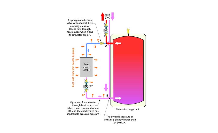
Still, the Achilles’ heel of a two-pipe buffer is that a small portion of the water returning from the load can flow backward through the heat source when it and its circulator are off. This creates unnecessary heat loss and reduces the temperature of the water supplied to the load.
One way to prevent this flow is to place a device that prevents flow until the differential “cracking” pressure across it reaches a specific value. A typical spring-loaded check valve or check cartridge insert in a circulator provides a cracking pressure in the range of 0.25 to 0.5 psi. However, sometimes the installed piping can create higher forward pressure differentials and prevent a standard spring-loaded check valve from blocking the undesirable flow through the inactive heat source.
A possible solution would be a spring check valve with a customizable cracking pressure.
Imagine a component that serves as a shell for spring-loaded check cartridges having more than 0.5 psi forward cracking pressure. Those cartridges are available. They use stronger springs to hold the valve’s disc against its seat. Change the cartridge, change the cracking pressure.
The body of the valve should have half unions at both ends that allow it to be easily removed from piping so different cartridges can be inserted. The valve body should also have a small air-bleed fitting that would allow air trapped behind the valve’s disc to escape when the system is being filled.
Another option is to use a differential pressure bypass valve that can be set as low as 1.0 psi forward cracking pressure. It replaces the need for the spring check valve, albeit at a higher cost. However, my searches haven’t found any such valves in sizes larger than 1.25 inches. We need larger sizes — at least up to 3-inch pipe size.
Better thermal storage tanks
Thermal storage is useful in many hydronic heating and cooling applications, especially those using renewable energy heat sources or electric thermal storage.
Figure 6 shows the concept for a thermal storage tank that I would like to have for several hydronic applications.
> FIGURE 6
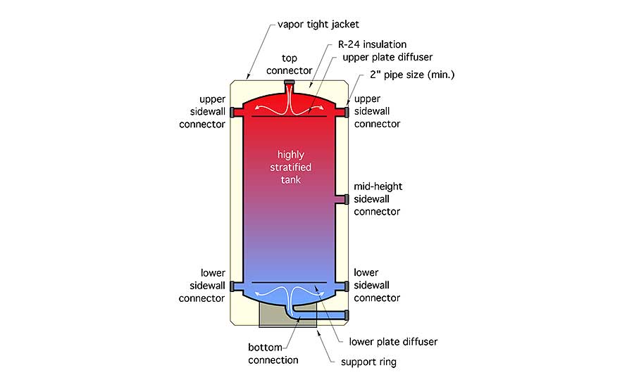
This tank would have very low rates of heat loss (or heat gain in cooling applications). I suggest R-24 (°F*hr•ft2/Btu) foam insulation capable of withstanding 200° F temperatures on all surfaces of the pressure vessel.
It would also have generously sized upper and lower sidewall connections located close to the top and bottom domes as well as at the very top and very bottom of those domes. All connections would be FPT, and no smaller than 2-inch pipe size. This allows for low entering flow velocities to preserve temperature stratification. It also creates very low head loss allowing the tank to provide hydraulic separation for multiple circulators. Reducer bushings could be used if smaller piping needs to connect to the tank.
The location of these main connections help ensure that all the water in the tank is fully “engaged” in thermal exchange rather than leaving the hottest water suspended above a level where it can be extracted from a sidewall connection several inches down the side of the tank, or the coolest water sunken below the active flow zone at the very bottom of the tank.
The tank would have internal flow diffuser plates that create a donut-shaped gap between the outside of the plate and the inner tank wall. These diffusers break up vertical flow jets within the tank caused by water entering from the very top or bottom connections. Flow passing through this annular gap would be moving very slowly, which helps preserve temperature stratification.
This tank could be piped in a two-pipe, three-pipe or four-pipe configuration. Multiple tanks could be joined in side-by-side “close-coupled” array. Drainage and top-side venting could be handled external to the main connections. Any unused connections can be easily plugged. Pipe insulation could butt and seal directly to a tank’s vapor-tight jacket. This helps prevent condensation when the tank contains chilled water. I’ll explore all the connection possibilities in a future column.
Dream on
Thanks for your indulgence of my musings. Perhaps some of these ideas are similar to those you’ve thought about. Perhaps some could serve as a launching pad for a future North American product. If so, have at it, manufacturers.
New products, even when they fit small niches in the market, can further enhance the benefits of hydronic heating and cooling systems.
To read Siegenthaler’s article: “5 products the hydronics industry needs” in pdf form, please see here.
Looking for a reprint of this article?
From high-res PDFs to custom plaques, order your copy today!


