Renewable Heating Design | John Siegenthaler
Transitions: Systems for simultaneous heating and cooling (Part 2)
What happens if there’s a simultaneous call for domestic water heating and cooling?
Image Source: DenBoma / iStock / Getty Images Plus
Last month, we discussed the use of hydronic heat pumps (air-to-water or water-to-water geothermal) for space heating, domestic water heating, cooling, and heat recovery ventilation. I presented a conceptual schematic for a system that could provide all four of these functions. It’s shown again in figure 1.
FIGURE 1
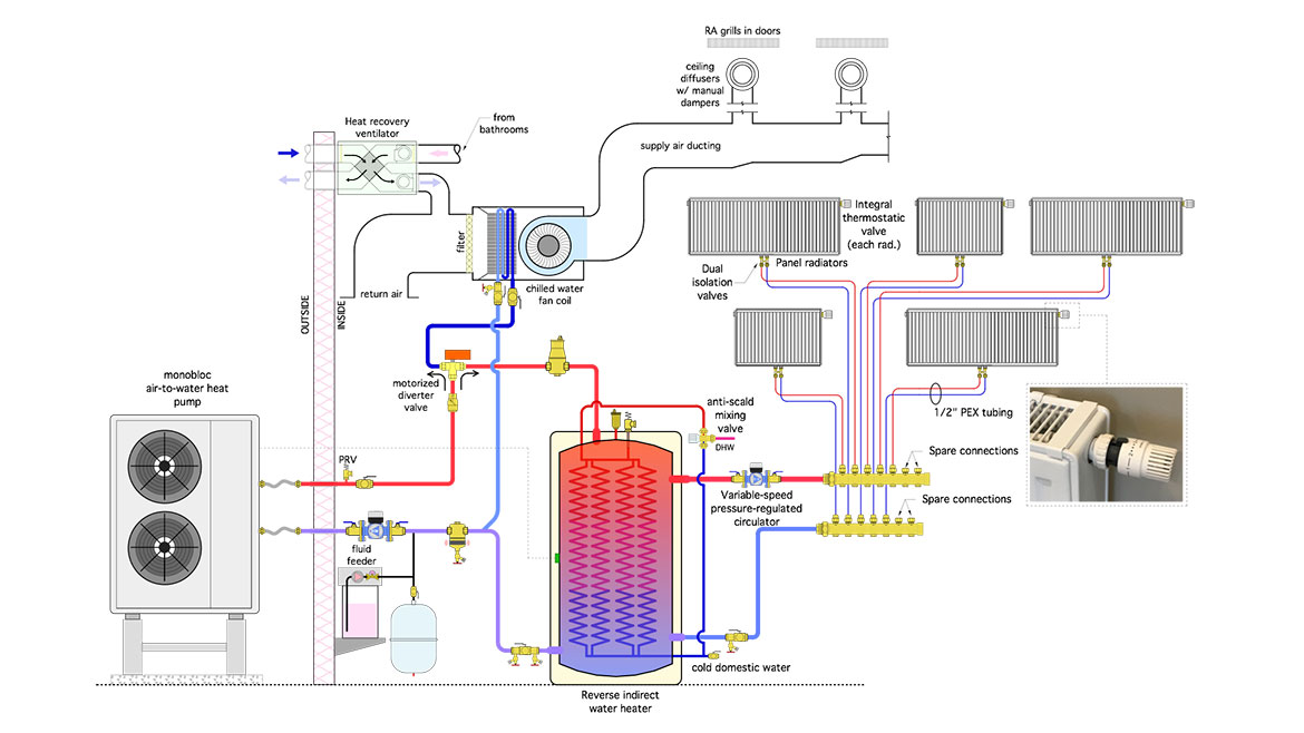
Image courtesy of John Siegenthaler
If you’re just looking at this for the first time - go back to last month’s column at to get a summary for how this system operates.
We left off with a question: What happens if there’s a simultaneous call for domestic water heating and cooling? This scenario is not only possible, it’s likely to occur often. All it requires is for someone to take a shower on a hot summer day when the home needs cooling.
The answer is that one of these mode (e.g., cooling or domestic water heating) has to take priority over the other.
For the system configuration shown in figure 1, my preference would be giving priority to maintaining the buffer tank temperature to ensure DHW delivery. The rationale is that raising the temperature of the buffer tank 15-20 ºF during cooling season, when outdoor temperatures are high, typically only requires a few minutes of heat pump operation - assuming that the DHW draw does not go on and on… If extended shower operation is part of the design goal I suggest including a supplemental DHW heat source, such as an electric tankless heater.
Some modern air-to-water heat pump have internal controllers allowing the priority between cooling and DHW production to be easily set. Some allow for priority override, in which the priority load is given a set time to operate, after which the lower priority load takes over - assuming it’s still calling for operation. Some also provide a “repeat cycle” function in which the priority and non-priority loads are automatically rotated into operation if and when a set time has elapsed.
For heat pumps without this control feature, the equivalent logic can be created using a repeat cycle time delay relay. Figure 2 shows the basic concept where the repeat cycle time delay relay is combined with two common 24 VAC DPDT relays.
FIGURE 2
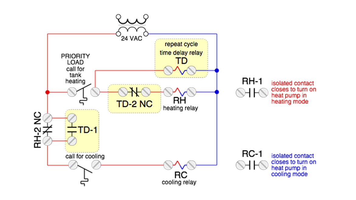
Image courtesy of John Siegenthaler
The repeat cycle time delay relay can be set for a specific on-time followed by a specific off-time. For example, the knobs or DIP switches on the relay could be set so that when the coil is energized it closes a normally-open contact - such at (TD-1) in figure 2, for 15 minutes, followed by holding that contact open for the subsequent 12 minutes. As long as the coil remains energized that cycle repeats every (15+12=27) minutes. Figure 3 shows an example of such a relay.
FIGURE 3
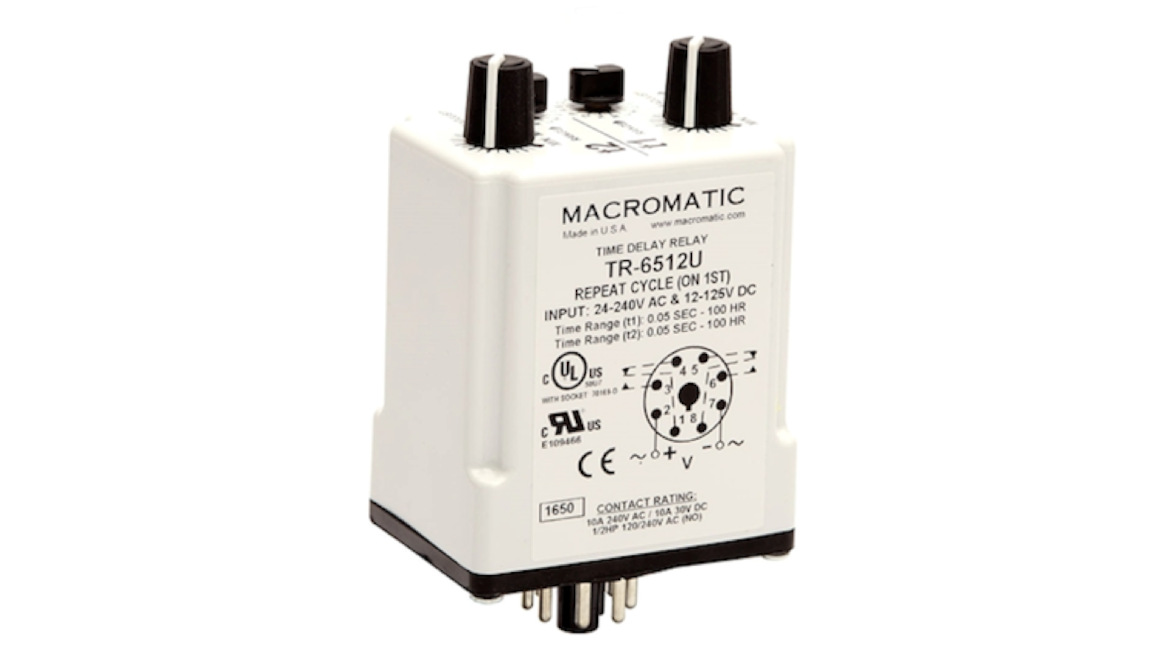
Image courtesy of John Siegenthaler
Further Refinement: Although steady state operation of the system shown in figure 1 is easy to understand, there’s an undesirable “glitch” that occurs when the system switches between heating and cooling modes.
Assume that the system controls are set to make heating the buffer tank a priority (e.g., to ensure adequate DHW delivery). If the system is operating in cooling mode the piping between the heat pump and the air handler is filled with chilled fluid, typically at a temperature of 45-50 ºF. When a call to heat the tank occurs the heat pump’s compressor and circulator shut off, and the heat pump begins a timing cycle of about 3 minutes before it can restart in heating mode. During that time the diverter valve has changed the flow path from the air handler to the buffer tank. BUT, the piping between the heat pump and the diverter valve still contains cold fluid. When the heat pump circulator turns back on this chilled fluid is pushed into the buffer tank. That effect may not be noticed by occupants, but its obviously undesirable from an efficiency standpoint.
This effect can also occur in reverse. Consider a case where the heat pump is operating in heating mode to boost the buffer tank temperature, and a priority call for cooling comes in. When the heat pump turns off, progresses through its 3 minute time delay, and then restarts in cooling, hot fluid in the piping between the heat pump and diverter valve will be pushed through the cooling coil. If the blower in the air handler is running, a slug of hot air gets pushed into the conditioned space. Although it might only last for a couple of minutes it’s guaranteed to produce complaints and call backs.
One way to prevent these unwanted slugs of cold and hot fluid from reaching portions of the system where they don’t belong is shown in figure 4.
FIGURE 4
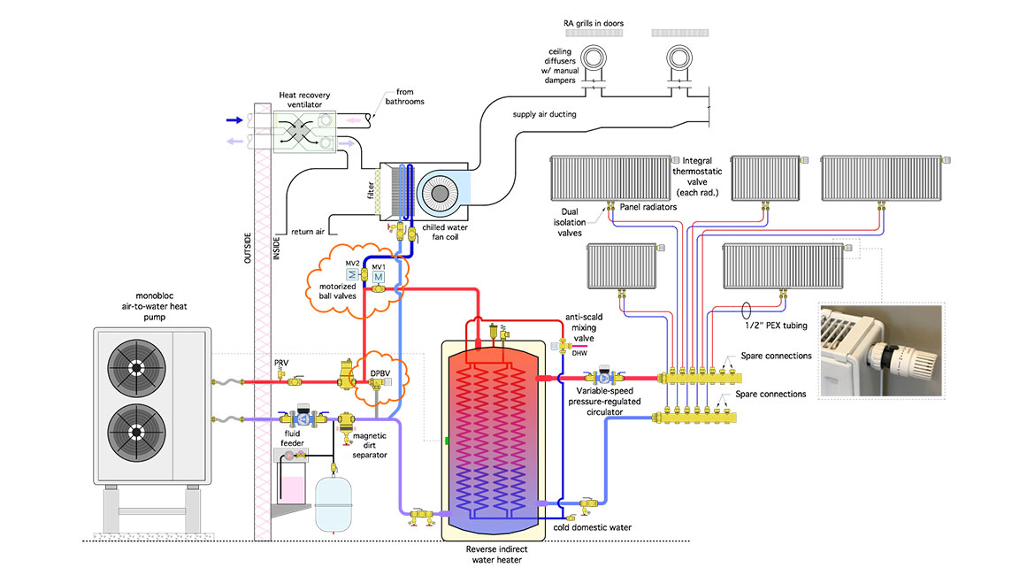
Image courtesy of John Siegenthaler
The only changes in this schematic, compared to Figure 1, is the use of two 2-way motorized ball valves (labelled as MV1 and MV2) rather than a single 3-way diverting valve, and the addition of a differential pressure bypass valve (DPBV). These components are shown within the orange clouds in Figure 4.
Like the motorized 3-way diverter valve in figure 1, the two 2-way motorized valves allows flow to be rerouted based on the system’s operating mode (e.g., heating or cooling). Unlike the 3-way valve, the 2-way valves, in combination with the differential pressure bypass valve (DPBV), also allows a “bypass mode” in which flow from the heat pump goes to neither the heating or cooling portions of the system. That mode occurs when both MV1 and MV2 are closed and the heat pump circulator is operating. Flow leaving the heat pump passes through the DPBV and back into the heat pump. This allows the heat pump to rapidly heat or cool the water to the required temperature for the pending mode before releasing it to the remainder of the system.
Some air-to-water heat pumps already contain the hardware and control logic to execute a bypass mode. For those that don’t, some type of temperature sensing controller is needed to determine when the fluid leaving the heat pump is approaching the desired supply temperature for the pending load, and signal either MV1 or MV2 to open.
It’s also important to set the opening differential pressure of the DPBV high enough so that:
- It remains closed when either MV1 or MV2 is open
- It, in combination with the heat pump circulator, allows the flow rate through the heat pump when both MV1 and MV2 are closed, to be at or above than the manufacture's specified minimum flow rate.
Another possibility is to substitute a normally-closed zone valve for the DPBV. It would only open during the transition between heating and cooling.
Details Matter: As the market for hydronic heating and cooling in homes continues to grow it’s important to pay attention to potential issues such as the mode transitions described above, and develop repeatable solutions that are as simple as possible and use readily available hardware. As a hydronics professional you wouldn’t tolerate chilled fluid being injected into your own DHW system, or bursts of warm air from your home’s cooling system. Don’t create systems that do any less for your customers.
Looking for a reprint of this article?
From high-res PDFs to custom plaques, order your copy today!


