Renewable Heating Design | John Siegenthaler
Modern hydronics technology can play well with future energy markets — Part 2
Image courtesy of onurdongel / iStock / Getty Images Plus.
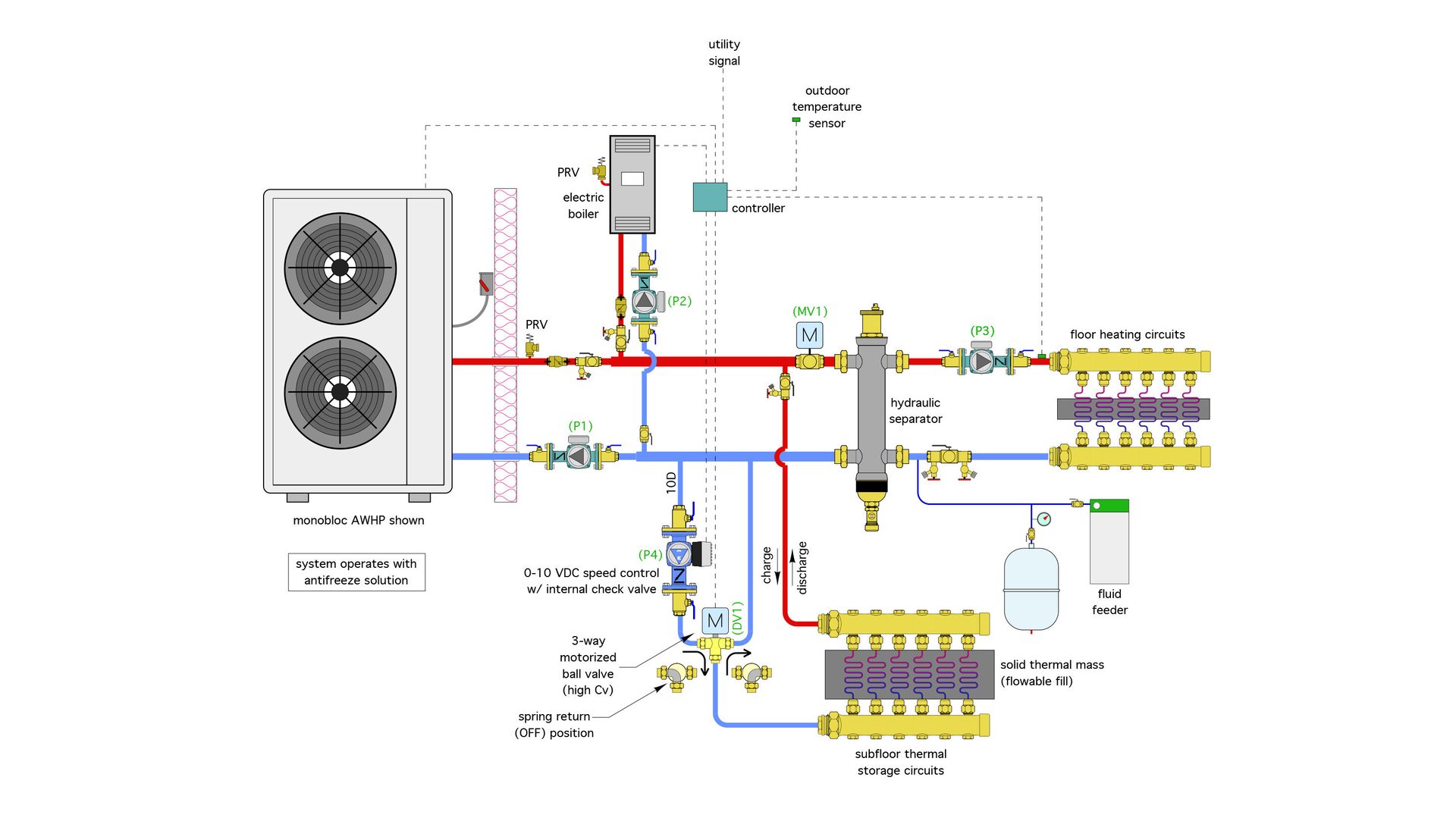
Last month, we discussed how solid thermal energy storage, combined with an air-to-water heat pump and an electric boiler, provides a platform to leverage time-of-use electrical rates in ways that can benefit customers as well as the utility providing the electricity. I introduced the system layout shown in Figure 1, and asked readers to figure out how it works.
FIGURE 1
I did provide some clues by listing the following five operating modes of the system:
- Mode 1: Heat Pump supplies floor heating directly;
- Mode 2: Electric Boiler supplies floor heating directly;
- Mode 3: Heat pump supplies heat to thermal storage, but with space heating override;
- Mode 4: Electric boiler supplies heat to thermal storage, but with space heating override; and
- Mode 5: Thermal storage supplies floor heating using outdoor reset control.
The simple stuff
Let’s start with modes 1 and 2: the heat pump (mode 1) or electric boiler (mode 2) supplies floor heating directly. The components involved in this mode are shown, in color, in Figure 2. The grayed-out components are not active in this mode.
FIGURE 2
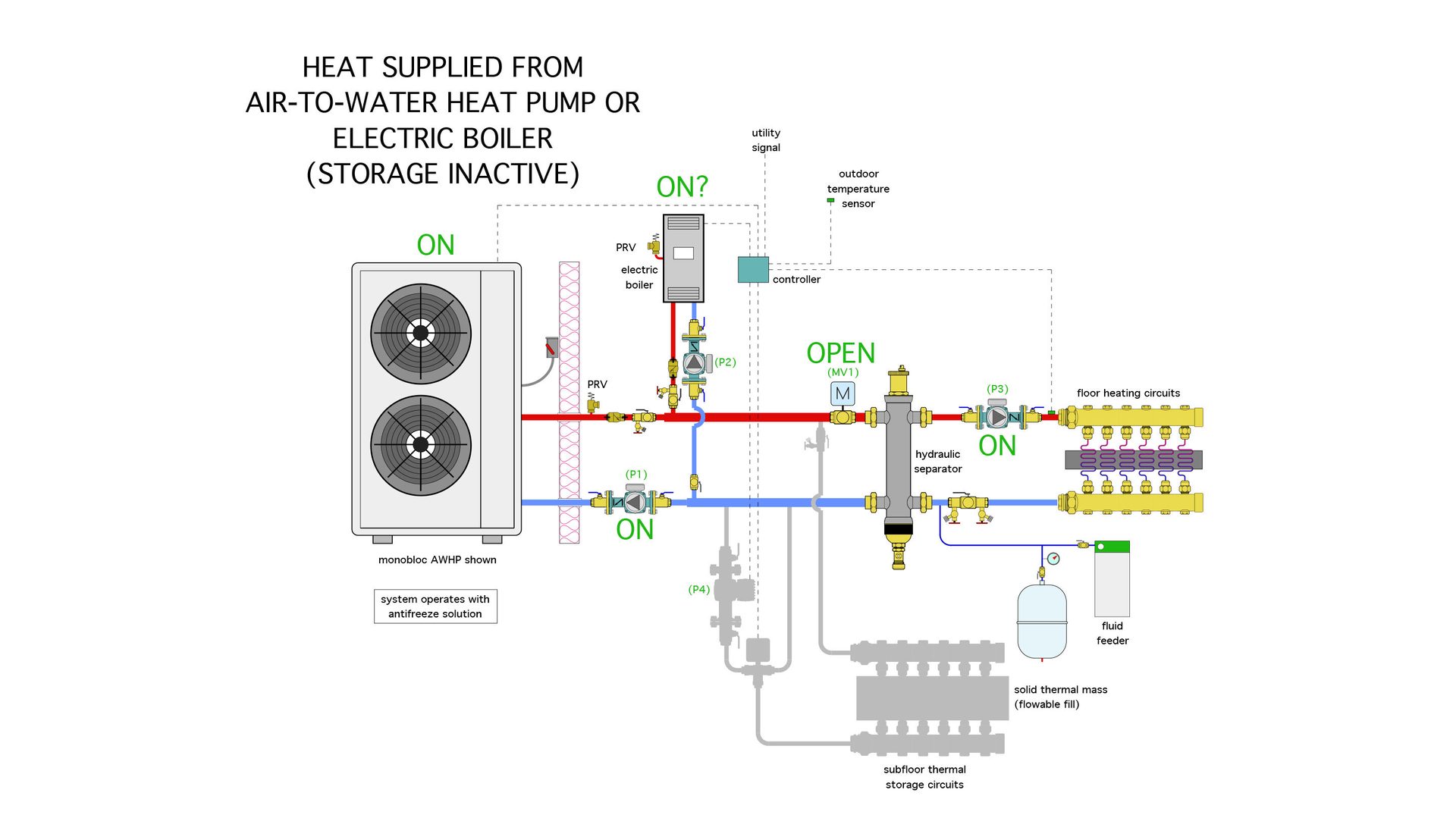
The heat pump and its associated circulator (P1) are operating. So is the distribution circulator (P3). A warm solution of propylene glycol and water is supplied to the red header. The motorized 2-way ball valve (MV1) has an on/off actuator with a spring return. When the actuator is unpowered, the valve is open. When 24 VAC is supplied to the actuator the valve closes. In modes 1 and 2, valve (MV1) is unpowered, allowing warm fluid to pass into the hydraulic separator which can accommodate different flow rates through the heat pump and the floor heating circuits and prevents interaction between the distribution circulator (P3) and the heat pump circulator (P1). It also provides air, dirt and magnetic particle separation for the system. Heated fluid flows from the hydraulic separator through the floor heating circuits and returns to the heat pump through the lower portion of the separator.
A similar flow path is used if and when the electric boiler is supplying heat to the system (e.g., mode 2).
It is possible for the heat pump and the electric boiler to operate at the same time. A typical control scenario would use the heat pump as stage 1 heat input to the system and only bring on the electric boiler as stage 2 when necessary to maintain the target supply water temperature to the floor heating circuits. The electric boiler also serves as a backup if the heat pump is down for service.
The heat pump and boiler circuits both contain check valves to prevent flow reversal, purge valves and pressure relief valves.
During modes 1 and 2, the supply water temperature to the floor heating circuits is regulated based on outdoor reset control. This keeps the supply water temperature and return water temperature as low as possible to maximize the heat pump’s COP.
Fill ‘er up
Modes 3 and 4 happen when the heat pump supplies heat to thermal storage (mode 3), and the electric boiler supplies heat to storage (mode 4). The components used in this mode are shown in Figure 3.
FIGURE 3
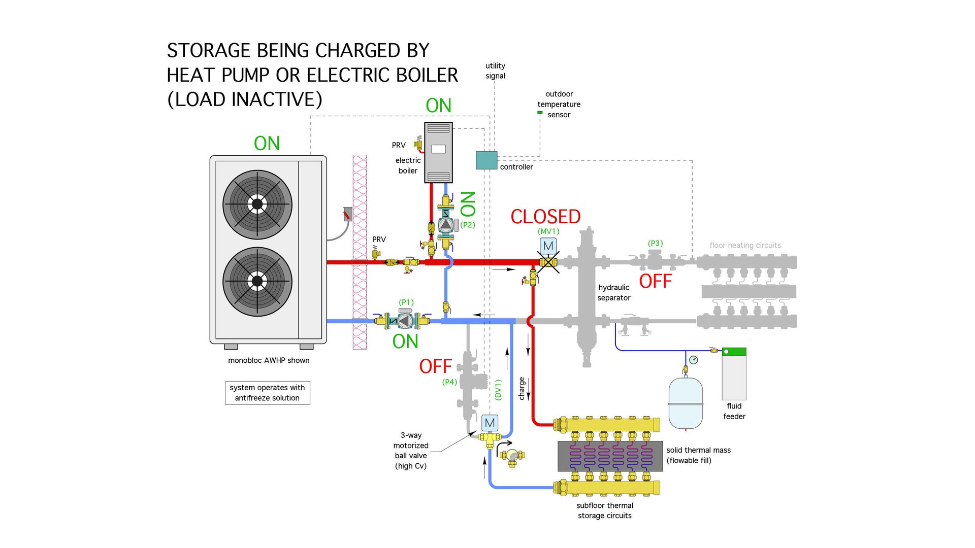
Figure 3 Image courtesy of Illinois Ready Mixed Concrete Association.
As in modes 1 and 2, either the heat pump or the electric boiler, or both operating simultaneously, supplies heat. The circulators associated with either active heat source are also operating. The motorized valve (MV1) is powered closed to prevent flow from entering the hydraulic separator. Circulator (P1) or (P2) force heated fluid through the tubing circuits embedded in the solid thermal mass. Cooler fluid returning from these circuits passes up through the diverter valve (DV1), which is in the powered position. From the diverter valve, the flow passes back to the heat pump, the electric boiler or both.
Modes 3 or 4 are active when off-peak electrical rates are in effect — typically mid-evening through early morning, and often all day on weekends and some holidays. The objective is to “charge” the storage with heat produced using the lower cost electricity. That heat can then be delivered to the building during subsequent times when on-peak rates are in effect.
Although flow is blocked on the left side of the hydraulic separator during these modes, the distribution circulator (P3) can continue to operate to provide flow through the floor heating circuits — if desired. Continuous circulation helps balance heat output across different areas of a heated floor slab. It’s particularly beneficial in buildings with large overhead doors. Without continuous circulation floor areas just inside such doors often cool faster than slab areas farther inside the building.
The fluid temperature supplied by the heat source(s) would increase as the thermal mass is charged. There would need to be an upper limit temperature for each heat source. Most current generation air-to-water heat pumps can operate with leaving fluid temperatures up to about 130° F. The electric boiler should be able to supply up to 180° F. However, the thermal capacitance of the solid thermal mass, combined with appropriate spacing of the embedded tubing, would likely keep the fluid temperatures well below these limits, and thus keep the COP of the heat pump as high as possible during the charging mode.
Comfort is priority one
In my opinion, any new approach for supplying heat to a hydronic distribution system must provide equal or better comfort when compared to a standard boiler supplying that same distribution system. If that’s not the case, the new approach, no matter how novel, is very unlikely to gain widespread market acceptance.
Sure, there will always be “hobbyists” willing to accept wider deviations from normal comfort for the sake of reducing energy costs. I know because I used to be one. But experience has taught me that the vast majority of consumers are not heating hobbyists. They want to be comfortable, based on their chosen setpoints, and without having to tinker with the system.
With that in mind, the system needs a way to detect if there’s a call for space heating while thermal storage is being charged and give priority to space heating. In this scenario, the heat pump or boiler would revert to supplying the floor circuits as described in modes 1 and 2. When the call for space heating is satisfied, or some other criteria are met, and assuming off-peak rates remain in effect, the system would revert to charging mode.
One approach is to temporarily suspend thermal storage charging to accommodate a call for space heating for perhaps an hour, and then switch the system back to charging. The thermal mass of the floor heating slab would limit the temperature drop in the heated space, making it essentially imperceptible over this short period when all heat is directed into storage. This characteristic also provides flexibility to fine-tune the control system based on the available off-peak time, the allowable variation in indoor temperature and the mass of the floor heating system. For example, thermal storage charging could be the priority over a certain “early” portion of the off-peak period, with space heating becoming the priority during the later portion of the off-peak period.
Remember injection mixing?
That brings us to mode 5: Space heating supplied from thermal storage. The active portions of the systems in this mode are shown in Figure 4.
FIGURE 4
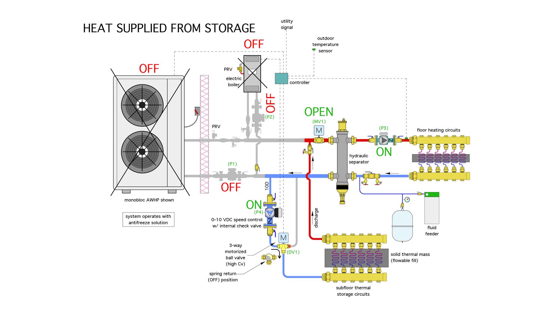
In this mode, the 3-way diverter valve (DV1) and the 2-way motorized ball valve (MV1) are both powered on to provide the flow routing shown in Figure 4. Check valves prevent reverse flow through either heat source.
The speed of circulator (P4) is regulated by a 0-10 VDC signal from the system controller. This allows the flow rate from thermal storage into the upper left port on the hydraulic separator to be varied. The “injected” flow from storage mixes with some of the return flow from the floor heating circuits to determine the supply water temperature to those circuits.
This is a variation on the concept of variable speed injection mixing, which has been used in thousands of hydronic systems over many years. The target supply water temperature to the floor circuits is again based on outdoor reset control. As the storage temperature cools the injection flow rate increases. At some point, the injection flow rate may equal the distribution flow rate. As the temperature of fluid delivered from storage continues to decrease, the injected flow will no longer be able to maintain the necessary target supply water temperature. At that point, the thermal storage subsystem would stop operating. The heat pump or electric boiler would take over heat supply (e.g, modes 1 or 2 described earlier).
Notice that the flow direction through the solid thermal mass during discharging is reversed from that occurring during charging. This provides desirable counterflow heat exchange (e.g., the fluid passing through the thermal mass circuits is moving toward storage material that tends to be at higher temperatures due to the flow direction present during the charging mode). This increases the average ∆T between the fluid and the thermal mass, allowing for higher rates of heat exchange when needed.
Where can I buy it?
The piping components and heat sources used in this system are all “off-the-shelf,” and available from several suppliers. However, to my knowledge, there are no currently available off-the-shelf controllers that can manage all the modes just described. A building automation system (BAS) could be configured to manage the system. Another possibility are low-cost and readily available microcontrollers such as Raspberry PI, and Arduino, that, with the necessary instruction code, could easily handle these requirements.
I encourage controller manufacturers to consider building products that could manage this type of system. The farther our energy markets lean toward electrification, the greater the demand for hydronic systems supplied by heat pumps. The more “creative” utility companies become with rate structures, the greater the incentive for thermal storage. Modern hydronics technology can pull all these concepts together into viable systems that provide superior comfort, reliable operation and “play well” with the future energy markets.
Looking for a reprint of this article?
From high-res PDFs to custom plaques, order your copy today!


