Hydronics Workshop | John Siegenthaler
Switching heat pumps between domestic water heating and cooling
Switching space heating to cooling, and vice versa.

Image courtesy of John Siegenthaler
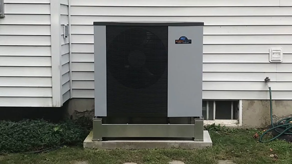
Air-to-water heat pumps and water-to-water geothermal heat pumps provide warm water for space heating and domestic water heating. They can also provide chilled water for cooling. In some systems, a single heat pump supplies all three of these thermal loads, though, in most cases, not at the same time.
Switching a hydronic heat pump system from space heating to cooling and vice versa, on a seasonable basis, is relatively simple. For example, the space heating load in the upper portion of the continental U.S. typically begins around late September and ends in April. The cooling season often begins in late May and runs into early September. In many locations, there’s a “dead band” of time when neither heating nor cooling are required. This allows plenty of time for a buffer tank, which might be used in both heating and cooling modes, to equalize to room temperature before needed to be heated or cooled. The system operating mode is changed at the thermostat, or perhaps a dedicated system mode switch with heat, off, and cool settings.
There are other locations that may require heating in the morning and cooling by the afternoon. There are several ways to do this. One approach is to not use the buffer tank for cooling mode. Route flow directly from the heat pump to the air handler that supplies cooling to the building. This requires a reasonable match between the heat pump’s cooling capacity and the cooling capacity of the air handler. Don’t connect a 5-ton rated single-speed heat pump to a 3-ton rated air handler. Instead, choose a reasonable chilled water supply temperature, likely in the range of 45° to 55° F, determine the heat pump’s cooling capacity at this temperature, and select an air handler that can provide about the same rate of cooling at this supply water temperature.
If the heat pump has a variable-speed compressor, there is more “wiggle room” when matching a single air handler to the heat pump. Just be sure the air handler’s capacity at the selected chilled water supply temperature is not lower than the minimum cooling capacity of the heat pump
If multiple air handlers are used, a variable-speed heat pump is usually a good match. To minimize short cycling, be sure the load from the smallest cooling zone is reasonably matched with the lowest cooling capacity of the heat pump.
If there are many independently-controlled cooling units, such as fan coils in each room, it’s probably best to have a buffer tank between the heat pump and all those zoned terminal units.
Quick switches
One situation that’s common in residential applications is when a single heat pump (air-to-water, or water-to-water geothermal) needs to supply cooling and domestic hot water, with the possibility of both loads calling for operation at the same time. In such cases, one load must have priority since a heat pump cannot operate in heating and cooling modes at the same time. Either load can be the priority load. Some heat pump systems even provide a commissioning menu in which the user can select which load has priority. If cooling is set as the priority, and the heat pump is producing hot water for domestic water heating, it stops, allows its internal pressures to equalize during a short two to three-minute time delay, then restarts to produce chilled water. If domestic water heating is set as the priority, and the heat pump is operating in cooling mode when a call for domestic water heating occurs, the heat pump stops, goes through a similar time delay, and restarts in heating mode.
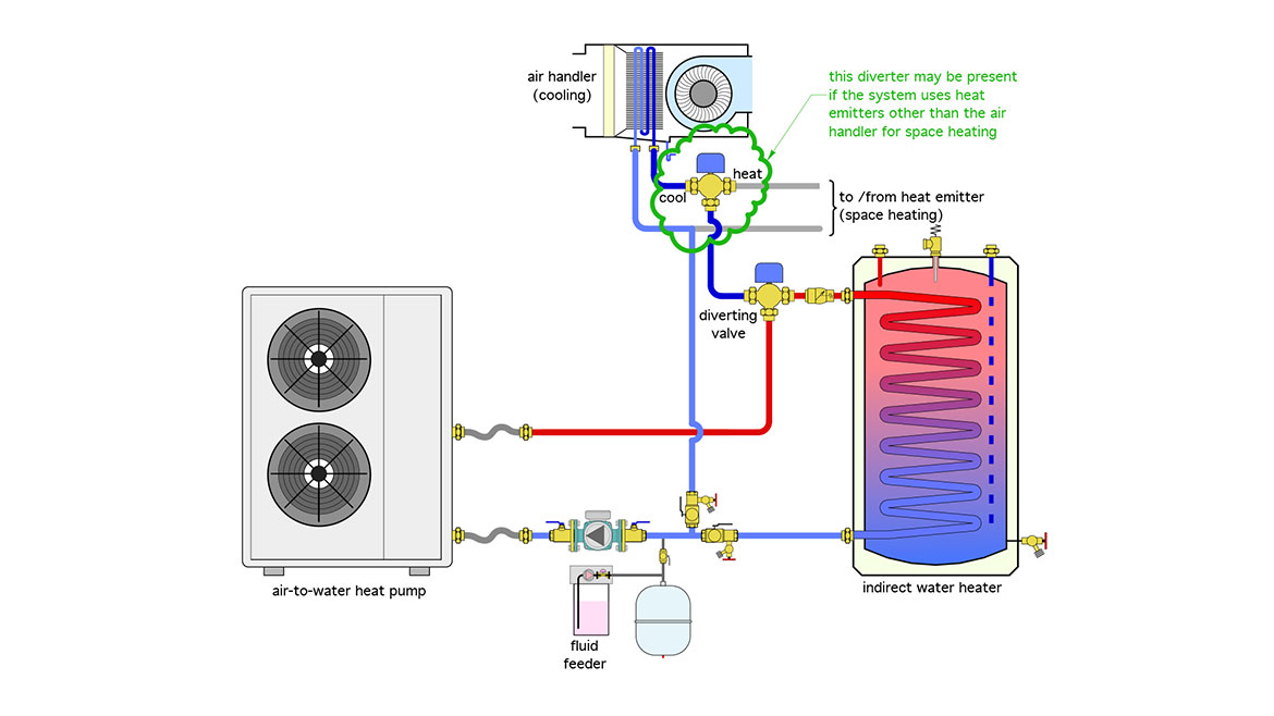
A typical system would have a diverting valve that routes the flow leaving the heat pump to either an air handler for cooling or an indirect water heater as shown in Figure 1.
FIGURE 1


This layout assumes “direct-to-load” piping in which the circulator providing flow through the heat pump also creates flow through the load paths. The lower diverter valve just determines if the flow from the heat pump goes to the indirect water heater or space conditioning. The latter could be space heating or space cooling. The upper diverter valve in Figure 1 directs flow to the air handler for cooling, or to some other distribution subsystem for space heating. If the air handler is used for both cooling and space heating, the upper diverter valve would not be needed.
Thermal consequences
Although this priority control concept is relatively simple, it can, at times, create undesirable operating conditions.
For example, consider what happens when a call for cooling occurs while the heat pump is operating in domestic water heating mode, and this occurs in a system where cooling takes priority over domestic water heating. The heat pump will shut off and the diverter valve will change to the cooling mode position. After two or three minutes, the heat pump will restart in cooling mode. At this point, there is still warm fluid in the piping between the heat pump and the diverter valve. As soon as flow resumes, this fluid will be pushed through the coil of the air handler. If the blower in the air handler is running, the occupants will feel a burst of warm air from the registers, which is obviously not what should be happening during a call for cooling. While this burst of hot air may only be noticeable for a minute or two as the fluid is cooled by the heat pump, it’s going to reoccur whenever a call for cooling takes priority over an active domestic water heating cycle.
A similar, albeit less noticeable effect will occur if domestic water heating takes priority over cooling. In this case, the cool fluid between the heat pump and diverter valve will be pushed into the coil of the indirect water heater. It will absorb some heat from the water in the tank, but probably not to an extent that would be noticeable at the hot water fixtures. Still, it’s an undesirable effect that should be eliminated.
The workaround
Both of these effects can be eliminated by temporarily preventing flow to either load following a switch from domestic water heating to cooling or vice versa. Figure 2 shows the piping needed for one approach
FIGURE 2


Valves (V1) and (V2) are either zone valves or ball valves with high Cv ratings. Valve (V1) opens when the system is operating in domestic water heating mode. Valve (V2) opens when the system is operating in either space heating or cooling mode. Valve (V3) is also a high Cv zone valve or motorized ball valve.
The Cv rating of all three valves is important. The Cv should be approximately equal to the flow rate through the heat pump. This will limit the pressure drop through each valve to about 1 psi (or about 2.3 feet of head loss). Don’t “cheat” by using valves with lower Cv ratings. They will just create a choke point that limits flow to the loads.
Assume the system is operating in DHW mode. Valve (V1) is open and valve (V2) is closed. A call for cooling occurs. The system responds by closing valve (V1) and keeping valve (V2) closed. Valve (V3) opens. The heat pump circulator operates creating flow through the the heat pump. The circulating fluid cools rapidly because it’s the only thermal mass upon which the heat pump is acting. When the temperature of this fluid reaches some predetermined setpoint, such as 55° F, valve (V2) opens, valve (V3) closes and the chilled fluid passes to the air handler’s cooling coil. The blower in the air handler could be running during this transition time to circulate air through the building’s ducting.
A similar logic and valve sequencing occurs when the system changes from operating in cooling to heating domestic hot water. Both valves close and flow circulates between valve (V3) and the heat pump. It warms quickly, and at some predetermined temperature valve (V1) opens allowing flow to pass to the internal heat exchanger of the indirect water heater.
Hard-wired logic
Some air-to-water heat pump systems come with the necessary valving and control logic to do what has just been described. For those that don’t, the logic can be created using a dual setpoint controller (2 independent setpoint temperatures and differentials), along with a couple of relays. The wiring is shown in Figure 3.
FIGURE 3


The wiring in Figure 3 assumes that some other control (likely within the heat pump) determines if cooling has priority over heating or vice versa. It also assumes that the heat pump turns on its circulator whenever it is operating. The relay labeled RP has its coil wired in parallel with the line voltage supplied to the heat pump circulator. This causes the normally open contacts in relay (RP) to close whenever the circulator is operating. These contacts pass 24VAC through the normally closed relay contact (R1-1NC) to power on valve (V3). At that point, the heat pump and its circulator are on, valve (V3) is open and all flow is circulating between the heat pump and valve (V3). Valves (V1) and (V2) are closed.
A temperature setpoint controller with two independent setpoint and differential adjustments, (or two separate setpoint controls, each with a single setpoint and differential adjustment), is also powered on as soon as the circulator starts up. This controller monitors the temperature of the water leaving the heat pump at sensor Ts in Figure 2.
Follow the sequence
Assume there’s a call for domestic water heating. Based on the values shown in Figure 3, valve (V1) would open when the temperature of the water leaving the heat pump reaches 125° F (assuming this is hot enough to adequately heat domestic water). As soon as the end switch in valve (V1) closes, 24 VAC is passed to relay coil (R1). This causes contact (R1-1NC) to open, interrupting power to valve (V3) causing it to close. Flow from the heat pump is now forced through (V1) and onto the coil of the indirect water heater. Valve (V2) remains closed. This control logic only allows water that has reached 125° F to flow to the indirect water heater and stops that flow if the water temperature drops to or less than 115° F. The heat pump and circulator would turn off as soon as the call for domestic water heating cleared.
A similar control sequence takes place upon a call for cooling. Valve (V3) opens as soon as the heat pump’s circulator turns on, but valve (V2) only opens when the water leaving the heat pump has dropped to 55° F. (V2) closes if the cooling call clears, or if the temperature at the supply sensor increases to 65° F or higher.
These setpoints and differential are only examples. They can be set as needed depending on the equipment selected.
There are likely other hardware configurations and control concepts that could achieve similar results. Whatever approach is used, the goal remains the same: Prevent hot blasts from registers at the start of cooling cycles as well as slugs of chilled water from entering the domestic water heater.
Looking for a reprint of this article?
From high-res PDFs to custom plaques, order your copy today!


