The Glitch & The Fix
3-zone radiant system peppered with problems

The Glitch:
An installer is asked to create a three-zone radiant floor heating system using a 5-ton (60,000 Btu/h) single-speed geothermal water-to-water heat pump as the primary heat source, and a mod/con boiler as the auxiliary heat source. The heat pump is supplied by 4 earth loops made of 1” HDPE tubing, with each loop being 500 feet long.
Each of the three zones will have a six-circuit manifold station with nearly identical circuit lengths. All the floor heating circuits are underfloor tubing with aluminum plates stapled tightly to the underside of the subfloor, and well insulated.
The designer sets up a primary secondary system where each heat source connects to the primary loop using a pair of closely spaced tees, as shown in Figure 1.
FIGURE 1
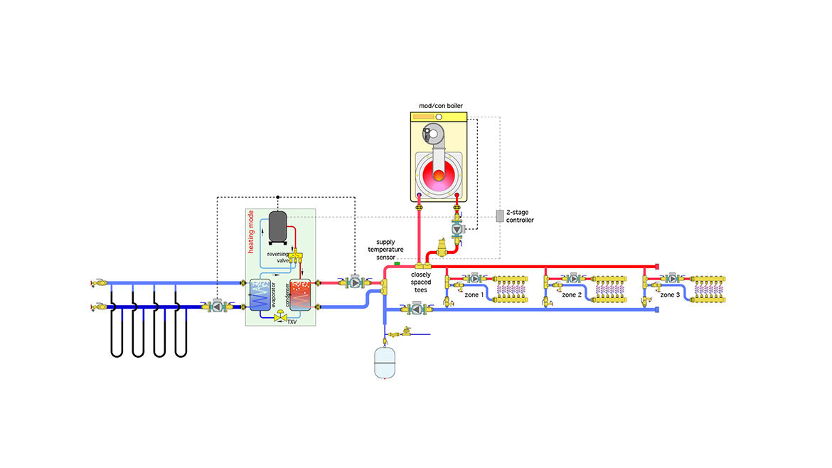
Each manifold station is also supplied from a pair of closely spaced tees installed in parallel “crossovers” of the primary loop. This keeps the supply water temperature to each manifold station approximately equal. The system has seven identical 1/25 HP circulators.
The installer provides two boiler drain valves to fill the earth loop and purge it of air.
The two heat sources are controlled by a 2-stage setpoint controller. When there’s a demand for heat from any of the zones the controller looks a the temperature at the supply sensor (Ts), and uses the following logic:
Stage 1:
If Ts ≤ 115° F then heat pump = ON
If Ts ≥ 117° F the heat pump = OFF
Stage 2:
If Ts ≤ 112° F then boiler = ON
If Ts ≥ 125° F the boiler = OFF
When put into operation, the heat pump short cycles. The boiler runs much longer than the heat pump.
Look over the system closely. Can you spot several details or settings that are either incorrect or missing? Can you propose an alternative design the would accomplish the same goals using less hardware?
The Fix
The system in Figure 1 is rife with errors and omissions.
- A 1/25 HP circulator might be adequate for a zone, but it’s not going to have sufficient flow and head to adequately supply the earth loop connected to a 5-ton heat pump. Minimum earth loop flow is often established based on maintaining turbulent flow, which enables good convective heat transfer. For a 1” HDPE pipe operating with 25% solution of propylene glycol antifreeze, and a minimum loop temperature of 30° F, that flow needs to be about 5 gpm per loop. Thus the overall flow passing through the heat pump is about 20 gpm. There’s no way a 1/25 HP circulator is going to come close to this requirement, especially when considering head loss through the earth loop circuits and the heat pump.
- There’s no air separator or expansion tank in the earth loop. Both are needed for optimum performance and pressure regulation in any closed-loop hydronic system.
- As shown in Figure 1, all earth loop circuits must be filled and purged in parallel. While possible, this requires much more flow than can be forced through typical boiler drain valves. Purging an earth loop of this size requires a flow of at least 16 gpm (4 gpm per loop). The valves used to force flow through this configuration should be at least 1.25” full port ball valves.
- Both circulators on the heat pump are “pulling” flow through their respective heat exchangers (e.g., the heat pump’s evaporator and condenser). These heat exchangers typically have high-pressure drops. This situation could cause the circulators to cavitate, especially if the static pressure in the earth loop is low. It always better to “push” flow into high flow resistance components. The same holds true for the boiler circulator.
- The controller on/off settings for Stage 1 are much too close, especially for a low thermal mass radiant panel. This is the likely cause of the short cycling.
- The temperature at which Stage 2 turns off the boiler is several degrees higher than when the heat pump turns off on Stage 1. This causes the boiler to remain on and likely drives more heat into the distribution system than necessary, which could lead to an overshoot in room temperature.
- The expansion tank is poorly placed relative to the primary loop circulator, this will cause the primary loop pressure to drop when the primary loop circulator is on.
- Two of the purging valves are upside down.
- There’s no pressure relief valve in the system.
- There will be some flow imbalance between the manifold stations due to the use of direct return distribution piping. The zone 1 crossover will get more flow than that of zone 2. The zone 2 crossover will get more flow than zone 3. Balancing valves need to be used in each crossover connected to direct-return piping mains, especially when the supply and return mains are long as would likely be the case in serving all three manifold stations.
- The supply temperature sensor should be downstream of both heat sources. As shown in Figure 1 it senses heat input from the heat pump, but not (directly) from the boiler. If the room thermostat wasn’t satisfied quickly, this would keep the boiler on until the return water temperature climbed a few degrees above 125° F.
- The air separator should be available to both heat sources, not just the boiler.
- The position of the backflow preventer and pressure-reducing valve on the makeup water system is reversed.
- There is no way to isolate either heat source from the remainder of the system if necessary for service.
One configuration that eliminates these issues is shown in Figure 2.
FIGURE 2
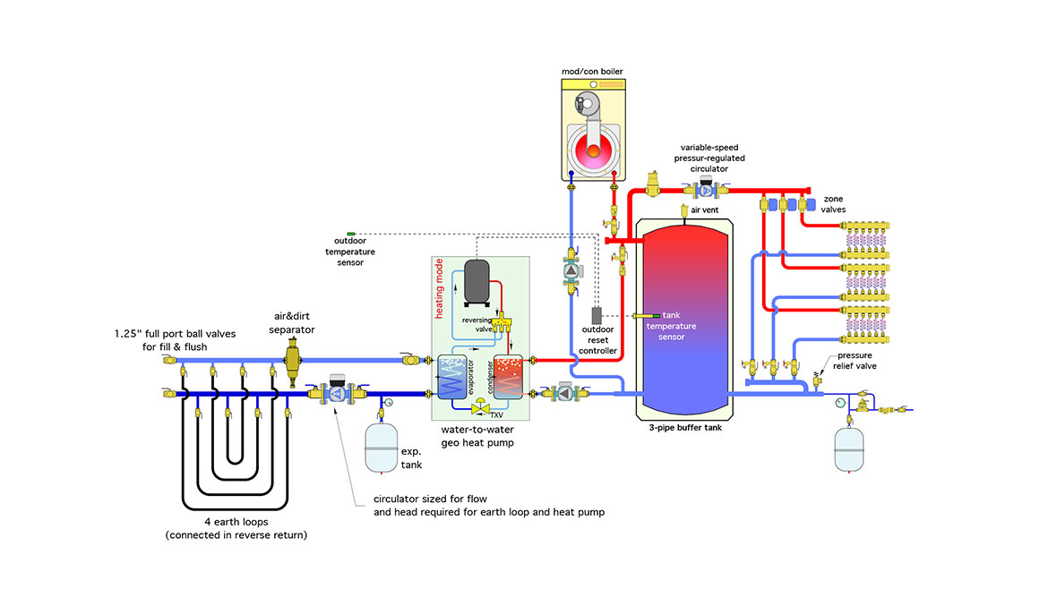
Both heat sources can operate individually or in parallel supplying heat to a buffer tank. The mass of the buffer tank stabilizes the system against short cycling.
The temperature of the buffer tank is controlled by a 2-stage outdoor reset controller rather than a setpoint controller. The heat pump is the fixed lead heat source, and the boiler the backup. As the outdoor temperature increases, the temperature of the buffer tank is reduced, which increases the COP of the heat pump and the efficiency of the boiler.
The distribution system is zoned with valves and supplied by a pressure-regulated variable speed circulator. This reduces the circulator count and greatly reduces the electrical energy required to operate the distribution system.
Each manifold station is supplied by home-run piping. The headers supplying each branch of the distribution system are as short as possible and generously -sized (maximum flow velocity of 2 feet per second). The headers are also configured as reverse return. This combination of design details, and the fact that all three manifold stations are identical, eliminates the need for balancing valves.
Each heat source can be isolated from the remainder of the system if necessary for service.
Check valves are used to prevent flow reversal or heat migration through either heat source when it is off.
A combination air/dirt separator and expansion tank have been added to the earth loop system.
Each earth loop can be isolated by ball valves, allowing for faster filling and flushing.
A pressure relief valve and properly configured make-up water assembly have been added to the system.
The earth loop circulator is pumping away from the expansion tank location, thus increasing pressure in the earth loop circuits and heat pump evaporator when operating.
Looking for a reprint of this article?
From high-res PDFs to custom plaques, order your copy today!