HYDRONICS WORKSHOP
John Siegenthaler: Peak performance
Modern hydronics technology offers unique solutions.

As interest and incentives build to transition space heating and domestic water heating systems away from fossil fuels and toward electricity, a somewhat predictable but only marginally quantified problem is developing. Two words describe it: Peak demand.
Properly sized heat pumps, especially those drawing low-grade heat from outdoor air (e.g., air-source heat pumps) can provide the majority of the space heating energy buildings require on a seasonal basis. Where the problem develops is on those few days (or even a few hours) where outdoor temperatures are at their lowest. This is when the heating capacity of any air-source bottoms out. It’s also when the typical electric resistance auxiliary heat for an air source heat pump kicks into high gear.
Recent work on the issue of peak demand as it pertains to New York State’s “Climate Leadership and Community Protection Act” (CLCPA) goals projects that somewhere around 2033, the traditional “summer peaking” situation that occurs when the electrical power demand of the state is considered as a whole, will change to a “winter peaking” situation as shown in Figure 1.
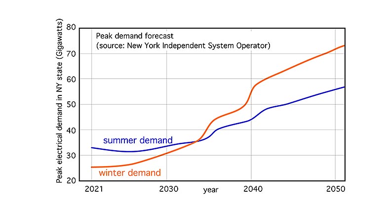
Furthermore, by 2050, peak demand (e.g., the required rate of energy delivery, not the required amount of energy) in just New York state could reach 73 Gigawatts (that’s 73,000,000,000 watts). I suspect that similar issues will develop in other states with cold winter climates and aggressive plans to eliminate fossil fuel in favor of full electrification.
This spike in demand wouldn’t be needed for long, in some cases, only a few hours per year. But when it’s needed it’s needed, and utilities, by law, must have ample reserve generation to meet it.
Peak generation capacity is also expensive — significantly higher than costs associated with baseload electrical generation. One estimate puts it this way: If the 100 hours of peak electrical demand could be flattened, the long-term avoided costs would be between $1 billion and $2 billion dollars — and that’s just for New York state.
What to do
Proponents of geothermal heat pumps are quick to point out that their systems only experience minimal increases in power demand when the outdoor temperatures bottom out for a few hours. Demand does increase because the geothermal heat pump runs more hours per day under low outdoor temperatures due to increased heating load. This higher “run fraction” temporarily pulls down the fluid temperature entering the heat pump from the earth loop, which also pulls down the heat pump’s heating capacity, and potentially requires electric resistance heat to make up the difference.
An air-to-air heat pump or air-to-water heat pump doesn’t have the stabilizing effect of a ground loop, and thus places more reliance on electric resistance heating during extremely low outdoor temperatures.
The geo heat pump proponents are correct in recognizing and promoting this difference. However, it’s somewhat short-sighted to conclude that building heating should all be transitioning to geothermal heat pumps based on projected peak power demand and the assumption that all supplemental energy comes in the form of electric resistance heating.
This is where the hydronics “playbook” has the potential to significantly improve the peaking problem as well as widen the options for heat sources.
One option in the playbook is thermal storage. It could be in the form of an insulated thermal storage tank that’s charged with heat during off-peak hours. Depending on the on-peak/off-peak kWh cost ratio, it may be feasible to charge the thermal storage tank to relative high temperatures (190°-200° F) using electric resistance heating elements, rather than limit the tank temperature to about 130° F using an air-to-water heat pump.
The use of relatively large thermal storage tanks to stabilize the differences between heat generation and heat demand is not new. Such tanks have been used for decades in systems supplied by solar thermal collectors, wood-based biomass boilers and electric boilers operating on off-peak electrical rates.
From a practical standpoint, these tanks are large, heavy and expensive. Nearly all mechanical codes require tanks larger than 119 gallons, and capable of being pressurized, to meet Section VIII of the ASME pressure vessel code, which definitely adds to their cost. The current situation with steel prices and supply chain issues only exacerbates an already costly option.
Solid mass
Another possibility is “solid” thermal storage in the form of a heat slab, or solid thermal mass under a heated slab. A concept for the latter is shown in Figure 2.
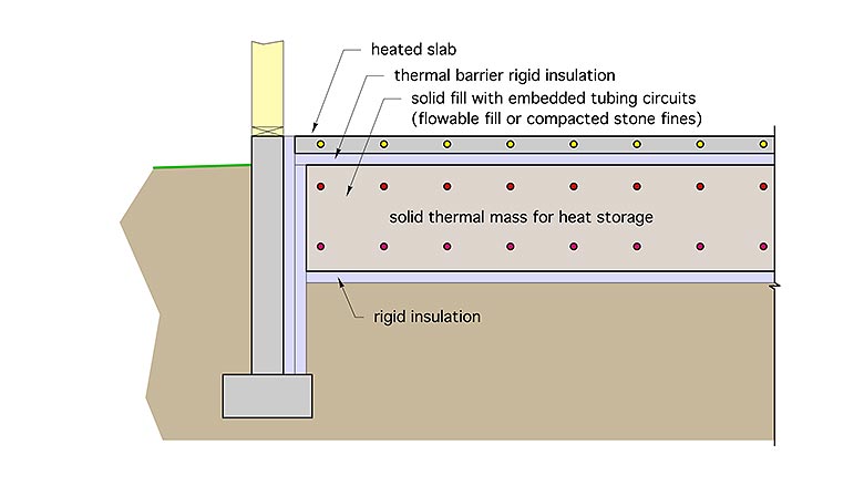
The upper slab contains embedded tubing and serves as the heat emitter for the space. It’s separated from the lower thermal mass by a layer of rigid insulation. The latter provides a high degree of thermal isolation between the lower solid thermal mass and the heating needs of the space.
The lower solid thermal mass could be a material such as compacted stone dust, or “flowable fill.” The latter has been used for filling large voids in sub grades for several years. It’s typically a mixture of cement, fine aggregate and fly ash or slab. It has acceptable load-bearing strength for use under slabs, (about 150 psi compressive strength) but less than that of structural concretes (typically 3,000-4,000+ psi compressive strength).
Whatever the fill material is, it needs to have reasonably good thermal conductivity as well as good heat capacity. Sand is not a good material for this fill because of its relatively low thermal conductivity due to limited contact area between grains.
Embedded tubing within this lower thermal mass carries water heated by an electrically-operated heat source such as an electric boiler, air-to-water heat pump, or geothermal water-to-water heat pump. This flow occurs when off-peak electrical rates are in effect. This allows heat to be stored without concern about overheating the conditioned space.
When on-peak electrical rates are in effect the preferred operating mode would be to shuttle heat from the lower thermal mass to the heated slab. If necessary, the heat source could also be configured to shuttle heat directly to the upper slab to maintain the desired comfort level.
The exact proportions of the various elements in this approach remain to be determined, most likely based on detailed computer simulation as a starting point, followed by proof-of-concept testing.
Dual fueling
Another hydronic option is to recognize that an existing fossil fuel boiler can serve as a “peaking” heat source for a building that has an air-to-water heat pump as a retrofitted primary heat source.
Why tear out a boiler that has several years of remaining life when it could serve this purpose, as well as provide backup if the heat pump is down for service?
Keeping that boiler in service could also potentially reduce the size and installation cost of the new heat pump.
During a utility power outage, the existing boiler can be powered from a small portable emergency generator that’s too small to run the heat pump. It might also be powered from modern customer-side battery storage systems such as the Tesla Powerwall or Generac PWRcell. Both of these backup options (e.g., the small generator or customer-side battery storage) provide “resiliency” beyond that available from an all-electric system that’s totally dependent on the utility grid.
Figure 3 shows a possible piping configuration where the new heat pump is piped in parallel with an existing fossil-fuel boiler.
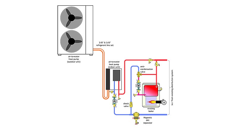
This configuration allows either heat source to operate independently of the other.
This piping configuration allows either heat source to supply the load. The “typical” control sequence would call for the heat pump to supply the required water temperature to the distribution system whenever possible and invoke the boiler only if that required supply temperature was not being achieved.
Notice that the existing (conventional) boiler has a thermal protection valve added to its near boiler piping. It’s there to prevent sustained flue gas condensation, assuming that there will be times when the return water temperature from the distribution system is below the dewpoint of the flue gases.
Strength through diversity
Although there are those who speculate that all energy needs can be met through electrification, the peak demand situation remains an inevitable hurdle, one that hasn’t been thoroughly and honestly examined to date, especially within the political realm. As states move closer to their projected renewable energy targets this issue will repeatedly separate aspiration from realization.
The versatility of hydronics technology to combine electrification with techniques such as thermal storage and a variety of fuel options such as renewable diesel, biomass and limited amounts of conventional fossil fuels provides a flexible and adaptive framework upon which to build future heating (and cooling) systems. It’s a sensible approach for the present as well as the years ahead.
petovarga/iStock / Getty Images Plus via Getty Images
Looking for a reprint of this article?
From high-res PDFs to custom plaques, order your copy today!


