John Siegenthaler: New in the neighborhood

This was quite a year for me on the home front. On fairly short notice, my wife and I found out that our daughter Heidi and her husband Andy would be building a house about 500 feet down the road from us. In February, we learned this project, which had been discussed from time to time as a “possibility,” was now a 100% “go,” and go now!
Heidi and Andy had worked up a rough layout for their new house, and my CAD system was soon humming along doing final dimensions, site planning, and — of course — drawing schematics for a hydronic heating system.
Andy and Heidi wanted to go with a geothermal water-to-water heat pump as the system’s main heat source. Their lot had plenty of space for a horizontal earth loop, and our local excavator, Wayne Hajdasz, had the 25 ton beast to quickly dispatch the dirt.
In June, we installed about 3,800 feet of 1-inch DR11 HDPE pipe in a curving 6-foot wide trench. Four parallel circuits go out at 6 feet deep and return at 4 feet deep. Figure 1 shows a cross section of the trench and its path relative to the new house.
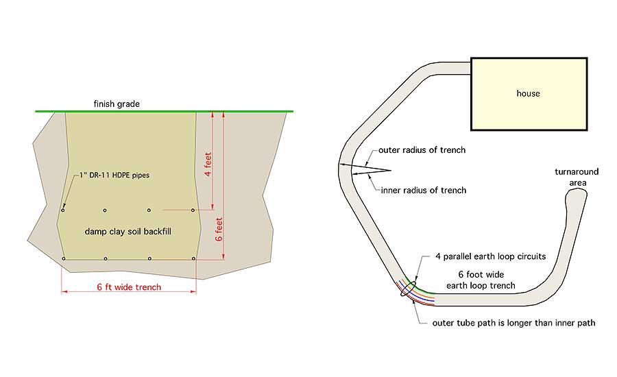
Figure 1.
PUNCHING THROUGH
The earth loop circuits pass through eight 3-inch diameter holes cast into the poured concrete wall. We used 3-inch diameter by 8-inch long solid polyethylene “rods” that were held in the wall forms using screws. Figure 2 shows these rods. After the walls were poured and the forms were stripped, a few taps with a hammer were all that it took to get the rods out, leaving eight smooth and aligned holes.
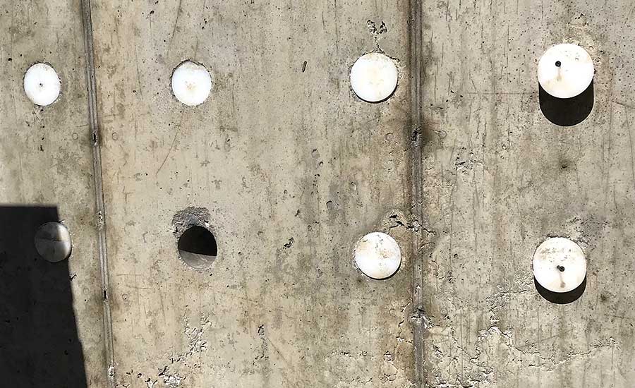
Figure 2.
The curving earth loop trench required the pipe along the outside of the trench to be several feet longer than the pipe along the inside of the trench. Wayne suggested that we could compensate for this by reversing the position of the pipes coming back to the house at the 4-foot depth. He manipulated that 6-foot ditching bucket with the skill of a baker frosting a cake to make the U-turn at the end of the trench, as shown in Figure 3.
We held the tubing in place along the bottom of the trench using 2-inch wide x 6-inch long landscape staples. Wayne then carefully back-filled over the lower layer of tubing with the loose dirt rolling in place parallel with the tubing so as not to push it out of position. Figure 4 shows us on the way out. You can see how Wayne carefully shelved the trench on both sides to guard against soil collapse — a real possibility with water oozing through clay soil.
By the time we got the earth loop piping back to the house, all the circuits lengths were within about 2 feet of each other. Although rolling 1,000-foot long coils of 1-inch HDPE in a muddy trench isn’t the nicest way to spend a June day, we managed pretty well. All the pipes were buried and backfilled in about six hours.
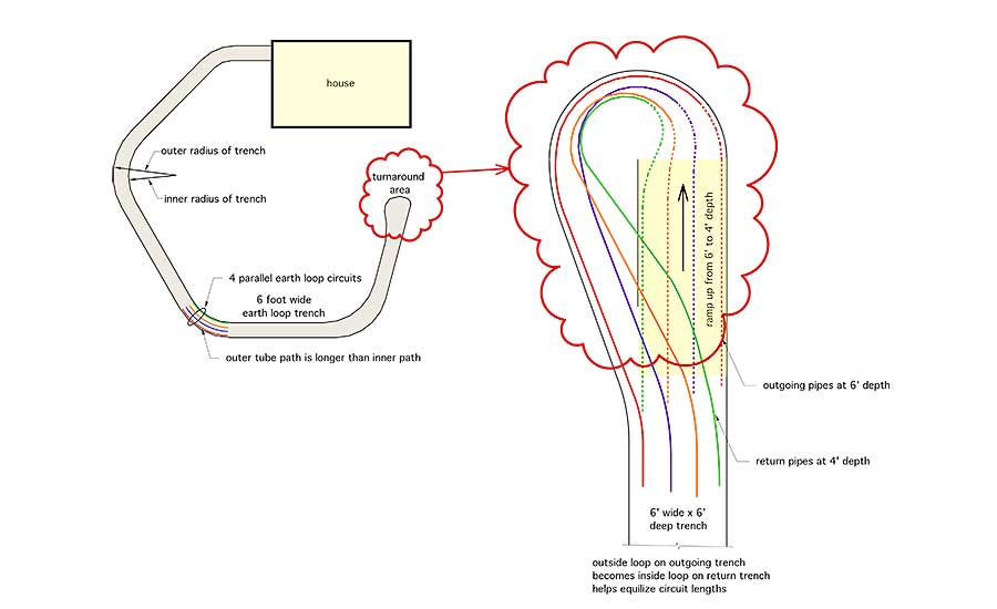
Figure 3.
NO BUTTS
There are no joints in any of the buried piping. It’s not that I don’t have faith in fusion joints. I definitely do. Done properly, both butt and socket fusion joints are stronger than the pipe itself. However, with the piping layout we used, no joints were necessary. I look at it as one of the trade-offs for wrestling those 1,000-foot coils down the trench and then back to the house.
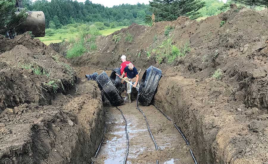
Figure 4.
The seals between the 1-inch HDPE and the 3-inch hole in the concrete wall were made using mechanically-compressed expansion collars. Just slip these donut-shaped assemblies over the pipes, push them into the 3-inch holes in the concrete wall and torque down the four stainless steel bolts seen in Figure 5. The soft rubber gaskets in the collars expand to provide a seal rated up to 20 psi. No caulk, no foam, no mess and no leaks.
The basement walls were specified to have 2-inch extruded polystyrene interior insulation running from the top of the wall to the top of the footing. An interior wall with 3.5-inch mineral wool batts was then constructed against the foam. This combination yielded an effective basement wall R-value of 24.4° F•ft2•hr/Btu.
My good friend and hydronic artisan Harvey Youker put together a great looking 1.25-inch copper manifold, complete with ball valves on both ends of all four circuits, as seen in Figure 6.
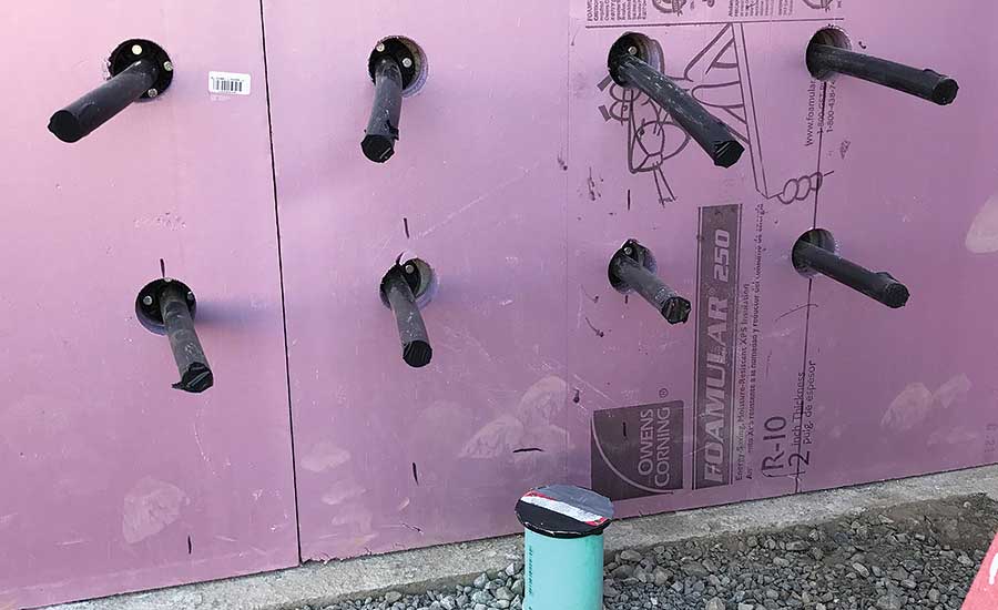
Figure 5.
The ball valves allowed us to flush each loop independently, using a relatively low purging flow rate compared to a situation in which all four loops would have to be flushed simultaneously. The ease of purging is another benefit on an interior earth loop manifold. The 1.25-inch ball valves at the right end of each manifold are where the flush cart was connected for filling and purging.
The previously described change of position of the earth loop circuits at the end of the trench allowed the four circuits to be configured for reverse return without having to add a third length of interior piping.
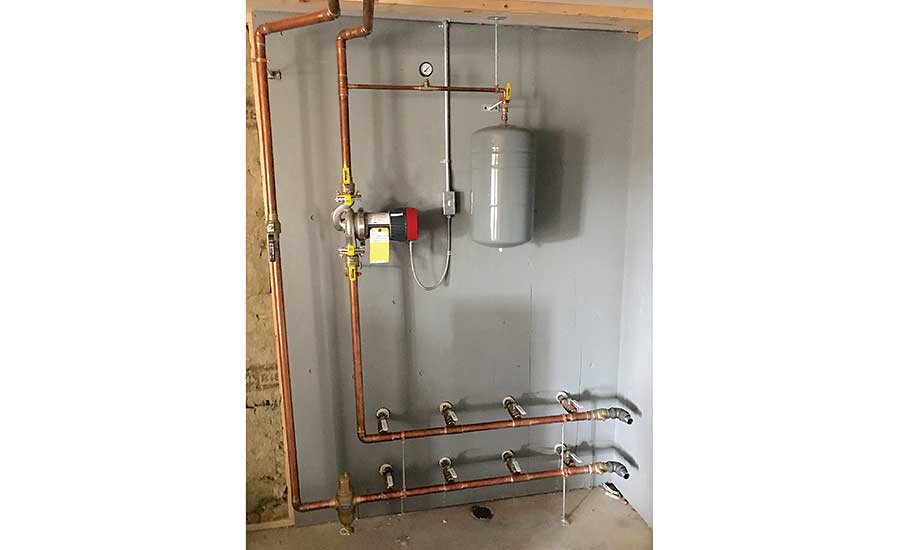
Figure 6.
Harvey fabricated some sleeves from 2-inch PVC pipe that go from the wall seal location through the foam and mineral wool insulation, and end just inside a neatly cut hole in the plywood interior finish wall, as seen in Figure 7.
I’m a strong believer that every closed earth loop should have an expansion tank, air separator and a dirt separator. In this system, we used a combination air and dirt separator, and a generously sized expansion tank. Harvey used threaded rod both horizontally and vertically to ensure the tank connection was well-supported.
Other trim includes a pressure gauge, expansion tank isolation valve and the engineered polymer pipe supports that hold the 1.25-inch copper supply and return pipes to the heat pump to the basement ceiling. These supports, seen in Figure 8, allow elastomeric foam insulation to be pretty close to continuous at the pipe supports.
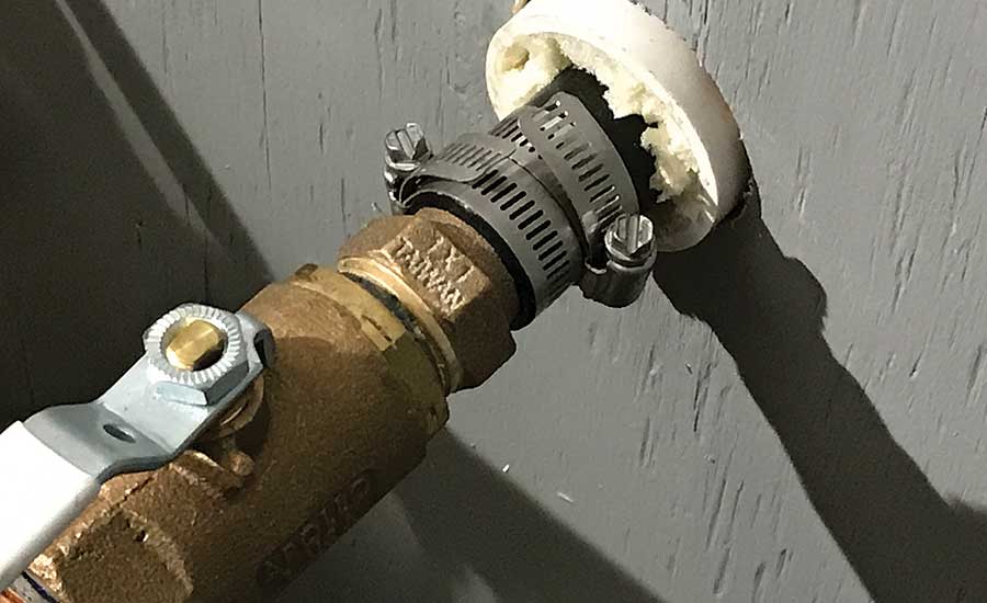
Figure 7.
Although not in place when these photos were taken, all interior earth loop piping will be insulated with 3/8-inch wall thickness elastomeric foam insulation to prevent condensation formation.
DOWN THE ROAD
Flow is created by a high-efficiency (ECM) circulator that has variable speed operation capability based on a 0-10 VDC control signal. At this time, we set the circulator for a fixed 12 gpm flow rate whenever the heat pump is operating. Still, if a promising control strategy comes along for flow modulation of the earth loop, and if that strategy can be “mapped” into a standard 0-10 VDC control output, it should be easy to implement it.
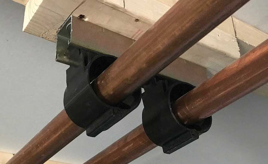
Figure 8.
By the time you read this, the snow will be falling in upstate New York, and the temperatures will be well below freezing on most days. Andy and Heidi should be enjoying a combination of warm floors and individually-controlled panel radiators. About 70% of the heat flowing from that distribution system will be solar energy that was temporarily stored several feet below finish grade. It’s a combination made possible by modern hydronics, the time-tested thermodynamic principles of heat pumps and the skill of accomplished craftsmen.
I’ll have more details coming on this system in future columns. In the meantime, may you and your family enjoy a blessed Christmas and a Happy New Year.
Looking for a reprint of this article?
From high-res PDFs to custom plaques, order your copy today!


