Cracking the Code
Circuit venting problem solved: Methods, connections and more

Why aren’t circuit venting methods accepted in every jurisdiction across the U.S.? Circuit venting is not an engineered design system, nor does it need an engineer’s approval. Circuit venting has been used as a common venting practice in plumbing systems since the 1920s. It is recognized in various plumbing codes throughout the U.S. and abroad.
Let us go back in time. It is 1982, and I am designing a large commercial plumbing project. The building is a large warehouse distribution center, with a grocery store and a car wash. The plans indicate 48 floor drains, eight water closets and six lavatories. After considering all of the different venting options — and instead of individually venting each fixture drain or using a combination waste and vent system for the floor drains — the designers choose circuit venting for the entire project. The rules using circuit venting for this project are as follows:
-
The horizontal branch drain is sized for the total drainage discharging into it (uniformly sized throughout);
-
No more than eight fixtures may discharge into the horizontal branch drain;
-
Slope for horizontal branch drain must not exceed 1 inch per foot;
-
Fixture branches (trap arms) installed on the horizontal plane;
-
Fixture branches (trap arms) are within trap to vent distance to the horizontal branch drain;
-
Each horizontal branch is provided with one relief vent located before the first fixture and one circuit vent located before the last fixture; and
-
Both dry vents are installed vertically and are 1/2 the size of the drainage piping.
The layout
Two restrooms are in the warehouse distribution center and grocery store. Each restroom contains four water closets and three lavatories (see Figure 1A and Figure 1B). One horizontal branch 4 inches in diameter serves eight water closets and one horizontal branch 2 inches in diameter serves six lavatories.
> FIGURES 1A, 1B, 1C and 1D
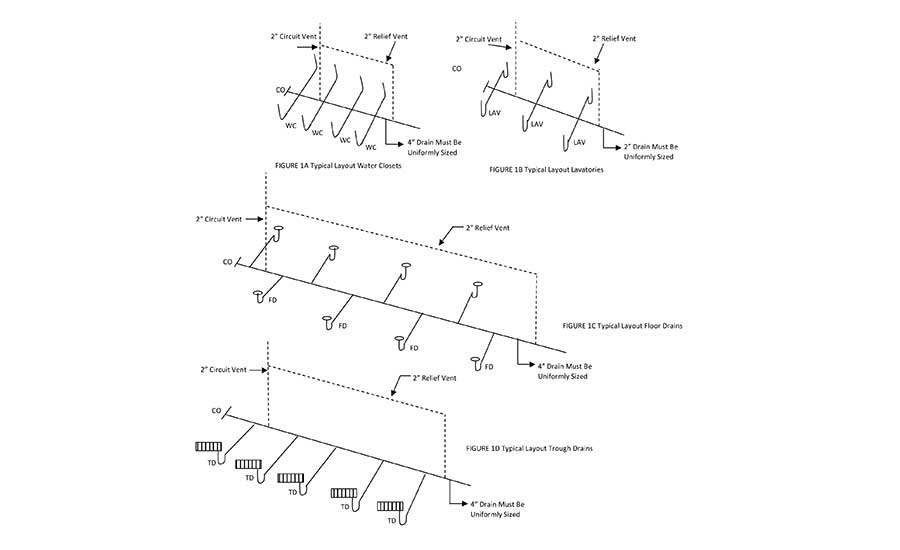
Each horizontal branch must be sized uniformly throughout its entire length. Fixture branches (trap arms) are installed in the horizontal plane with a wye or wye and 1/8 bend to maintain low flow velocity. No vertical portions are permitted between the fixture branch (trap arm) and trap.
The horizontal branch is considered the vent and must maintain a slope of no more than 1 inch per foot. Each fixture branch (trap arm) is within trap to vent distance from the horizontal branch. One vent is located before the first fixture and one vent before the last fixture. All dry vents were installed vertically and are 1/2 the size of the drainage piping.
For the series of floor drains located in the warehouse, the horizontal branch drain is 4 inches in diameter (see Figure 1C). Each horizontal branch drain includes a battery of eight floor drains installed with a wye or wye and 1/8 bend to maintain the horizontal plane and within a distance from trap to vent. There are no vertical portions to create an s-trap. Two vents are installed for each horizontal branch drain one-half the size of the drainage piping (2 inches in diameter).
The car wash includes five trough drains (one for each bay), and the horizontal branch drain is 4 inches in diameter (see Figure 1D). Fixture branches (trap arms) are installed in the horizontal plane and within the distance between the trap and vent. One vent is located before the first fixture and one vent before the last fixture. All dry vents were installed vertically and were 1/2 the size of the drainage piping (2 inches in diameter).
Fast forward to 2018; circuit venting design is still a viable option for venting a battery of fixtures regardless of the occupancy. The principle remains the same; oversize the drainage piping, no more than eight fixtures on the horizontal branch drain and the circuit vent installed between the two most upstream fixture drains (trap arm) on the horizontal branch.
This method is like the long-proven methods of wet venting and combination waste and vent methods, which also use the airspace above the waste flow level for venting fixtures connected to a horizontal drain pipe. The system relies on the oversizing of the drain pipe.
As with other horizontal wet venting methods the main section of the horizontal vent pipe is intended to be installed horizontally without vertical offsets, with each fixture drain (trap arm) connected “independently” to the horizontal drain to keep flow turbulence at a minimum and not create an s-trap. The air for venting the fixtures circulates in the top half of the horizontal branch drain pipe.
The horizontal drainage branch must also be uniformly sized to establish consistent flow characteristics and the free movement of air. Because it is uniformly sized for its full length, the horizontal branch will be oversized for its entire length.
The developed length of the vent pipe, along with the number of drainage fixture units connected thereto, must also be considered when sizing the vent system. The amount of air that a given pipe size can convey depends on its length. The effect of friction increases as pipe length increases and has a greater effect on the flow of air. If the friction increases to such a level that the vent is not able to prevent pressure differentials from exceeding 1 inch of water column, the vent pipe size must be increased to compensate for this effect.
The methods
The methods used to size a circuit vent must meet three criteria:
-
Horizontal branch drain is uniformly sized for the total drainage discharge (drainage fixture units) into the horizontal branch;
-
Circuit vent is sized based on the total drainage fixture units connected to the horizontal branch drain but not less than 2 inches in diameter; and
-
Total developed length of the circuit vent.
All plumbing codes contain requirements for circuit venting methods and all have the following principles, such as those illustrated in the 2018 Uniform Plumbing Code.
911.1 Circuit vent permitted. A maximum of eight fixtures connected to a horizontal branch drain shall be permitted to be circuit vented. Each fixture drain shall connect horizontally to the horizontal branch being circuit vented. The horizontal branch drain shall be classified as a vent from the most downstream fixture drain connection to the most upstream fixture drain connection to the horizontal branch.
> FIGURE 2
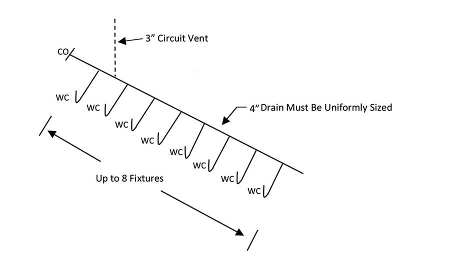
> FIGURE 3

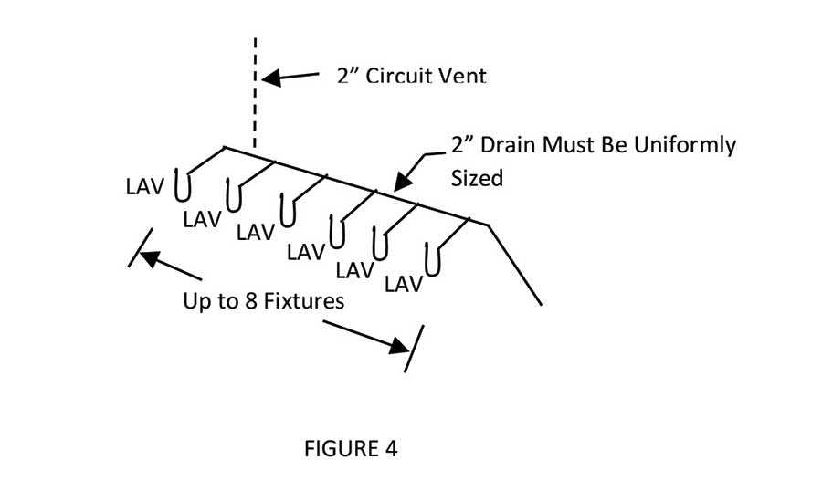
Circuit venting involves up to eight fixtures and a single vent. A dry vent connects between the two most upstream fixture drains (trap arms) on the horizontal branch. The horizontal branch serves as a wet vent for the battery of fixtures (see Figure 2 and Figure 3). This includes water closets, showers, bathtubs and floor drains (floor outlet fixtures). Also, fixture drains (trap arm) that connect in the horizontal plane to the horizontal branch drain above the floor level may include wall hung water closets, sinks and lavatories (see Figure 4). The horizontal branch is serving as a wet vent for the battery of fixtures.
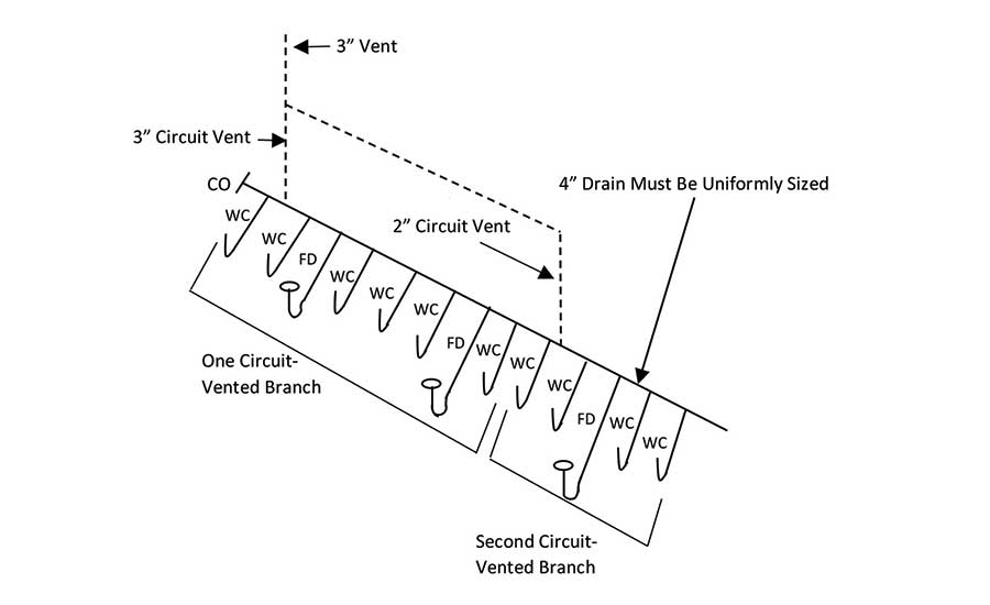
911.1.1 Multiple circuit vented branches. Circuit vented horizontal branch drains are permitted to be connected together. Each group of a maximum of eight fixtures shall be considered a separate circuit vent and shall be in accordance with the requirements of this section.
> FIGURE 4
> FIGURE 5
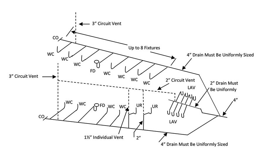
Circuit vented branches may connect either in series or parallel. Each group of up to eight fixtures must be considered as a separate circuit vented branch and installed accordingly. The concept of multiple circuit vented branches is that horizontal flow in a drain pipe does not require a large quantity of air to balance the pressure (see Figure 5).
Where more than eight fixtures are circuit vented, an additional circuit vent must be provided. One vent is required for each set of eight fixtures in the battery (see Figure 6).
> FIGURE 6
911.2 Vent size and connection. The circuit vent shall be not less than 2 inches (50 mm) in diameter, and the connection shall be located between the two most upstream fixture drains. The vent shall connect to the horizontal branch on the vertical. The circuit vent pipe shall not receive the discharge of a soil or waste.
Connections
The circuit vent must connect between the two most upstream fixture drains (trap arm) and rise vertically to allow proper circulation of air. The dry vent is located so that the most upstream fixture discharges past the vent connection, thereby washing that section of pipe and preventing the buildup of solids. When back-to-back fixtures are installed, the vent is connected between the most upstream pair.
The circuit vent is sized based on the drainage fixture units connected to the horizontal branch drain but not less than 2 inches in diameter. Unless specified in Chapter 9 for a specific size of vents, the size of vent piping is determined based on the number of fixture units connected thereto in accordance with the Table 703.2 of the Uniform Plumbing Code. Therefore, the circuit vent is no different but may not be less than 2 inches in diameter.
911.3 Slope and size of horizontal branch. The slope of the vent section of the horizontal branch drain shall be not more than 1 inch per foot. The entire length of the vented section of the horizontal branch drain shall be sized for the total drainage discharge to the branch.
The principle of a circuit vent is that the drainage branch is entirely horizontal. A maximum pitch of 1 inch per foot ensures that the branch remains horizontal without any vertical offsets. The horizontal drainage branch must also be uniformly sized to establish consistent flow characteristics and the free movement of air. Because it is uniformly sized, the horizontal branch will be oversized for the entire length.
911.3.1 Size of multiple circuit vent. Multiple circuit vented branches shall be permitted to connect on the same floor level. Each separate circuit vented horizontal branch that is interconnected shall be sized independently in accordance with Section 911.3. The downstream circuit vented horizontal branch shall be sized for the total discharge into the branch, including the upstream branches and the fixtures within the branch.
Each circuit vented branch must be uniformly sized based on the total drainage load on that branch, including any drainage load from upstream branches and any additional fixtures within the branch.
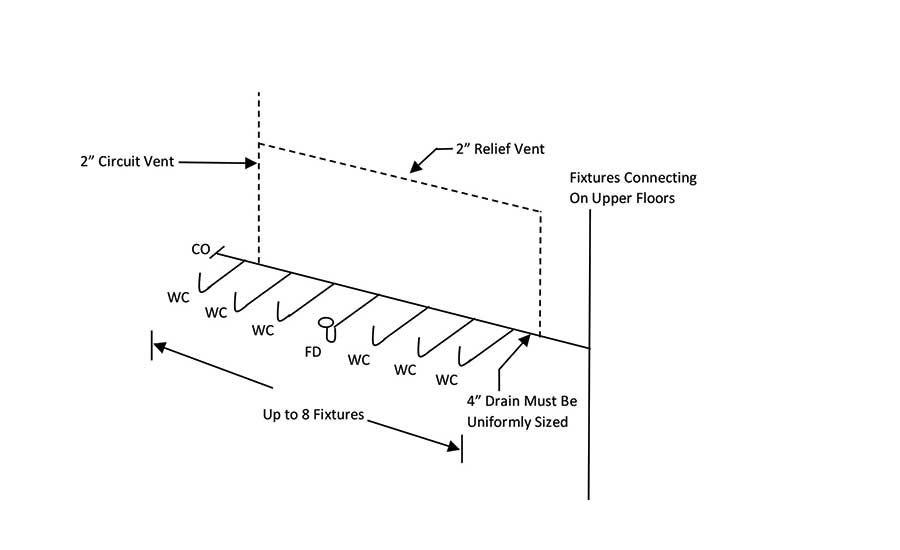
911.4 Relief vent. A 2-inch (50 mm) relief vent shall be provided for circuit vented horizontal branches receiving the discharge of four or more water closets and connecting to a drainage stack that receives the discharge of soil or waste from upper horizontal branches.
If a circuit vented horizontal branch connects to a drainage stack that is receiving drainage discharge from floors above, a relief vent is required if more than three water closets connect to the circuit vented horizontal branch. The relief vent will prevent any pressure differential in the drainage stack from affecting the horizontal branch by relieving the pressures (see Figure 7).
> FIGURE 7
911.4.1 Connection and installation. The relief vent shall connect to the horizontal branch drain between the stack and the most downstream fixture drain of the circuit vent. The relief vent shall be installed on the vertical to the horizontal branch.
The relief vent must connect between the stack and the most downstream fixture on the horizontal branch. All vents must be installed vertically.
911.4.2 Fixture drain or branch. The relief vent is permitted to be a fixture drain or fixture branch for a fixture located within the same branch interval as the circuit vented horizontal branch. The discharge to a relief vent shall not exceed 4 fixture units.
Unlike the circuit vent, which must be dry, the relief vent is permitted to serve as a drain for fixtures installed within the same circuit vented branch.
911.5 Additional fixtures. Fixtures, other than the circuit vented fixtures, are permitted to discharge to the horizontal branch drain. Such fixtures shall be located on the same floor as the circuit vented fixtures and shall be either individually or common vented.
Where additional fixtures (other than the circuit vented fixtures) are located on the same floor as a circuit vented branch, such fixtures are allowed to connect to the circuit vented branch. The additional fixtures must be separately vented, and the additional drainage load of those fixtures must be considered in sizing the circuit vented branch. This provision is intended to allow the connection of lavatories, urinals and similar fixtures that are in the same area as the circuit vented fixtures (see Figure 5).
Problem solved, and as codes evolve, the requirements are refined and revised to incorporate various sizing and the location of vents. In recent years, the plumbing industry worldwide has increasingly become more cognizant of the value of fresh water for human consumption, which ultimately has led to the design and installation of plumbing products with greater water efficiencies. As time goes by we will see various changes in our drain, waste and vent piping configurations, and rest assured IAPMO will be there every step of the way.
Stay tuned and check back for the 2021 Uniform Plumbing Code. RJ 2.0
"This article was originally posted on ww.reevesjournal.com."
Looking for a reprint of this article?
From high-res PDFs to custom plaques, order your copy today!


