John Siegenthaler: How to wire fresh air dampers
The 2018 version of NFPA 54 prescribes methods for providing this air into confined spaces using one or two openings to outside space.
All fuel-burning boilers require adequate amounts of combustion air. Most atmospheric boilers also required air circulation to carry away heat loss from boilers’ jacket and flue piping.
The manner in which this air is provided is governed by building and mechanical codes, and those codes typically reference NFPA 54. The 2018 version of NFPA 54 prescribes methods for providing this air into confined spaces using one or two openings to outside space.
Consider a situation where the code requires two 12-inch-by-12-inch openings in the exterior wall of a mechanical room to provide the necessary airflow to the boiler. The openings can have louvers to minimize rain and snow entry. They can also have screens, typically with a mesh size no smaller than ¼-inch to prevent birds, mice or other critters from getting inside these openings.
When it’s minus 10° F outside, those holes in the wall work very well. Frigid air pours into the lower opening as warmer air stratified near the mechanical room ceiling floats away through the upper opening.
Article Index:
- Only when needed
- The exception
- A delayed approach
I’ve been in mechanical rooms where those who didn’t understand the importance of these openings had stuffed them full of fiberglass insulation, or covered them with cardboard and duct tape. That’s understandable based on their concern over frigid air pouring in and warm air pouring out, but it’s absolutely not permissible from a code standpoint. The boiler’s got to breathe.
Only when needed
I like to specify motorized dampers to minimize unnecessary air entry into mechanical rooms in cold climates. They open to allow air exchanger when the boiler is operating and are closed at all other times. Figure 1 shows a pair of these dampers, one near the mechanical room floor and the other near the ceiling.
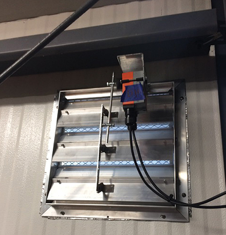
The damper blades are connected by a linkage that is moved by a motorized actuator. The blades pivot open when there’s a call for boiler operation and are closed by a spring return mechanism in the actuator as soon as the boiler turns off. The damper actuators typically have isolated end switches that close to verify when the blades reach their fully open position. Actuators on motorized dampers can take 30 to 90 seconds to fully open to the point where the end switch is closed.
Most codes require a safety interlock on motorized dampers that prevents the boiler from operating if the dampers end switch is not closed. The intent is to prevent situations where a boiler in a relatively air-tight mechanical room is starved for oxygen and becomes likely to produce higher levels of carbon monoxide, overheat the space, or both.
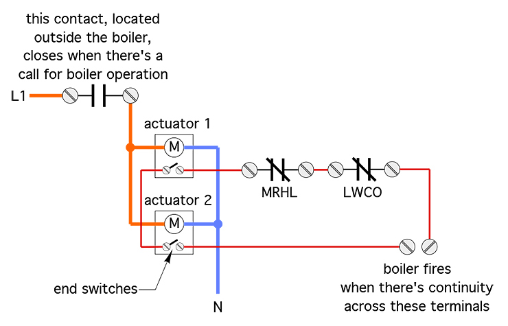
The typical wiring for such an application supplies power to the damper actuators when there is a call for boiler operation. When the damper is fully open, the isolated end switch in the actuator closes. A low-voltage circuit wired through the end switches completes the “call” for boiler operation.
If the boiler is equipped with other safety devices such as a low-water cutoff (LWCO) or a manual reset high limit (MRHL), the normally closed contacts in these devices are wired in series with the damper actuator end switches. The boiler is allowed to fire and remain in operation as long as all these safety-proving contacts remain closed. If any closed contact opens, the boiler stops firing.
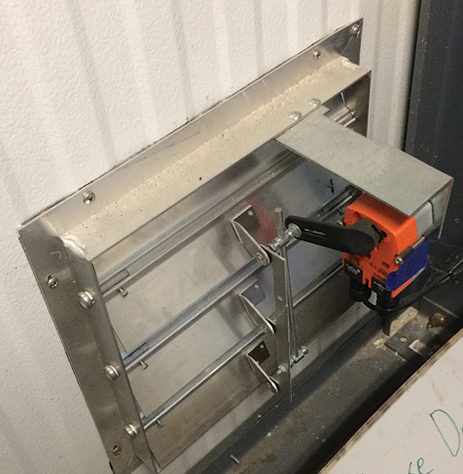
Figure 2 shows one wiring configuration that provides this safety “logic.”
The wiring in Figure 2 assumes the damper actuators operate on 120 VAC. A similar wiring arrangement is possible for damper actuators that operate on 24 VAC. The thin red lines represent a circuit with all four switch contacts in series. When all four contacts are closed, this circuit provides continuity across the terminals that enable the boiler to fire.
The exception
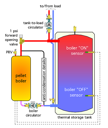
Not all boilers lend themselves to the wiring shown in Figure 2. One example is a pellet boiler that turns on and off based on the temperature of two sensors located within wells attached to a thermal storage tank. Figure 3 shows an example of a typical setup with this type of boiler.
The pellet boiler operates completely independent of any external calls for heat from the balance of the control system. Instead, the boiler’s internal controller monitors the temperature of the upper tank sensor. When that temperature drops below some minimum value, the boiler turns on.
It continues to operate until the temperature at the lower tank sensor reaches some upper limit. This control strategy helps ensure long operating cycles for the pellet boiler, which improves thermal efficiency and reduces emissions.
While this method of boiler on/off control makes sense from an efficiency and emissions standpoint, it presents a challenge when combined with the need for motorized fresh air dampers. If the boiler operates solely from its internal controls, how can motorized dampers with internal end switches be integrated into the control sequence?
A delayed approach
One solution to this issue is shown in Figure 4.
This circuit connects the 120 VAC actuator motors on the dampers to terminals inside the boiler that go to 120 VAC whenever the boiler is in a firing cycle.
Due to differences between boilers, designers need to determine exactly what terminals can be used for this “signal.” For example, on some boilers, the source of 120 VAC may be parallel wiring with the boiler’s circulator.
However, if the circulator doesn’t turn on at the beginning of the firing cycle, due to temperature controls inside the boiler, another source for this voltage must be used. It must go “live” at the very beginning of the firing cycle and remain live until all combustion inside the boiler ends.
If there is no internal source of 120 VAC for this purpose, there may be a source of 240 VAC, 24 VAC, or some other voltage (AC or DC). In that case, a relay with a coil voltage matching the internal source voltage can be used. The contacts of that relay would pass the necessary voltage (120 VAC or otherwise) to the damper actuators.
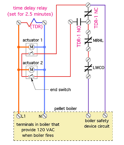
Figure 4 shows the coil of a 120 VAC time-delay relay wired in parallel with the actuator motors and the circulator. This coil is energized at the same time as the actuator motors. The time-delay relay begins its set countdown as soon as the coil is energized. When the countdown time expires, the contacts of the relay move.
The right side of the circuit shows the “safety train” for the boiler. It consists of a low-water cutoff (LWCO) and manual reset high limit controller (MRHL) wired in series. This series string is extended through the normally closed contact of the time-delay relay.
The latter remains closed until the countdown time set on the relay has elapsed. Thus, when the boiler’s internal controller initiates a burn cycle, there is a closed series string across the boiler’s safety device terminals. However, the end switches in the damper actuators, which have not yet closed, are not part of that series string.
The countdown time on the time-delay relay would be set to allow sufficient time for the motorized damper to fully open and the ends switches to close. I suggest a countdown time that’s at least ten seconds longer than the longest measured opening time of the damper actuators.
When the relay’s delay period has elapsed, it opens its normally closed contacts and closes its normally open contacts. The latter puts both actuator end switches in series with the normally closed contacts in the MRHL and LWCO. These four closed contacts represent normal operating conditions for the duration of the firing cycle.
If any of these four contacts open, the boiler’s “safety train” opens and the pellet boiler begins its burnout sequence. Assuming normal operation, the dampers remain open for the entire firing cycle. When that cycle ends the springs in the actuators close the dampers. This sequence repeats each time the pellet boiler fires.
A small but significant detail embodied in the schematic of Figure 4 is that the LWCO and MRHL controllers, which are often mandated by code, are always present in the boiler’s safety circuit, regardless of the status of the damper actuator end switches.
Perhaps a time will come when pellet boilers will “internalize” this control logic and provide dedicated terminals to which the damper end switches can be connected. Until then, this provides a simple solution.
This article was originally titled “Boiler breath” in the March 2018 print edition of Plumbing & Mechanical.
To read Siegenthaler’s article “Boiler breath” in pdf form, please see here.
Looking for a reprint of this article?
From high-res PDFs to custom plaques, order your copy today!


