John Siegenthaler: How to pipe multiple water-to-water heat pumps
How to pipe multiple water-to-water heat pumps.
Water-to-water heat pumps supplied from closed earth loops are ideal heat sources for low-temperature hydronic floor-heating systems.
Most current-generation water-to-water heat pumps can deliver water temperatures up to about 120° F when necessary. That's sufficient to supply several variants of radiant panel heating as well as properly sized panel radiators and low-temperature convectors.
When paired with heat pumps, radiant panels should be constructed so they can deliver design-load output at the lowest possible supply-water temperature. The lower that temperature can be, the higher the coefficient of performance (COP) of the heat pump.
WHEN ONE WON’T DO
Single-phase water-to-water heat pumps are available in nominal capacities up to about 5 tons (60,000 Btu/h). Some suppliers offer two independently controlled heat pump assemblies — each rated for a nominal 5-ton heating capacity — in a single enclosure, effectively making the unit a two-stage, 10-ton heat pump.
When design heat loads are larger than what can be handled by a single heat pump, designers may choose to use multiple heat pumps in a staged configuration. The piping for these configuration can be very similar to that used for a multiple-boiler system. Each heat pump should be connected to a common header assembly in parallel with the other heat pumps. Figure 1 (page 14) shows one possible configuration.
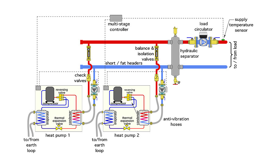
Figure 1.
In this system, flow through each heat pump is provided by individual circulators. The condenser inlet and outlet ports of each heat pump connect to a “short/fat” header system that leads to a hydraulic separator, which isolates the pressure dynamics of the heat pump circulators from the pressure dynamics of one or more load circulators. The hydraulic separator also provides high air, dirt and magnetic particle separation for the system. The separator also allows the flow rate on the heat-pump side to be different from the flow rate on the load side.
The short/fat headers shown in Figure 1 should be sized for a flow velocity in the range of 2 feet per second based on the total flow rate that could pass through them. This keeps the pressure drop along the headers very small. In situations where two or three heat pumps are mounted close to each other, the header piping size is typically held constant. If more heat pumps need to be lined up, the header size can also be stepped.
Some might argue the headers should be set up in reverse-return in order to equalize flow rates through each heat pump. While it’s true properly done reverse-return headers do, in theory, help with balancing flow rates, a counter argument is that by keeping the pressure drop along the headers very small in comparison with the pressure drop through the heat pumps, the difference in the unbalanced flow rates will be very small.
That difference is easily corrected by using a balancing valve within each heat pump sub-circuit, as shown in Figure 1. The balancing valves can also be fully closed to isolate one side of the heat pump sub-circuit during purging, or if a heat pump must be removed for servicing. The cost savings achieved by not using reverse return piping, and not having to use ball valves in place of the balancing valves, should cover the higher cost of the balancing valves.
Another advantage of generously sized headers relates to circulator sizing. If the pressure drop along the headers is very small, each circulator only has to provide slightly more head than required to sustain the design flow rate through its associated heat pump.
Most heat pump manufacturers specify a flow rate in the range of 2.5 to 3 gpm/ton (12,000 Btu/h) of heating capacity. Those flow rate would produce a water temperature rise of 9.6° and 8°, respectively, across the heat pump. The head loss of the heat pump at these flow rates is usually provided as a table or graph in the product specifications. If the fluid passing through the heat pump condensers is a mixture of water and antifreeze, these flow rates should be increased slightly to compensate for lower specific heat. The head losses should also be adjusted upward based on the concentration of antifreeze used.
ONE SUPPLIES MANY
Another piping option for multiple heat pumps is shown in Figure 2.
This system uses one variable-speed circulator to provide flow through all the heat pumps. When a heat pump is called into operation, its associated motorized ball valve opens. When this valve reaches its fully open position, an internal end switch within the valve’s actuator closes. That closure serves as the trigger to turn the heat pump on. The valve actuators are equipped with spring-return mechanisms that close the valve as soon as power is removed from the actuator.
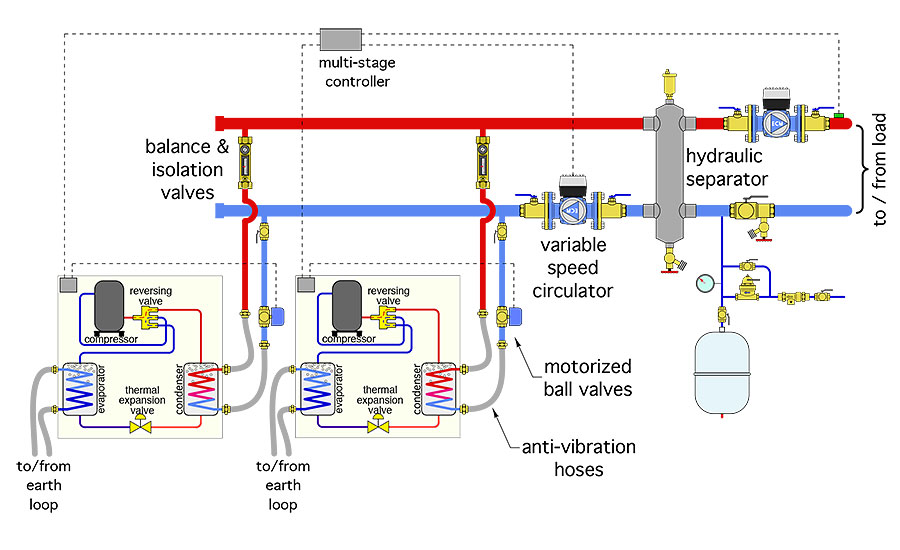
Figure 2.
The variable-speed circulator should be set in “constant ∆P” mode and at a pressure differential just slightly above that required by one heat pump. The circulator should be capable of providing the total flow rate required by all heat pumps at this differential pressure.
When one of the heat pump valves opens, there will be a momentary drop in differential pressure across the circulator. The electronics within the circulator feel this deviation from the set ∆P and quickly respond by speeding up the motor to restore the set differential pressure. When a heat pump turns off, its motorized ball valve closes, causing a momentary increase in differential pressure.
The circulator responds by slowing down to restore the set differential pressure. Think of this control response as cruise control for differential pressure. Whenever the circulator slows down, its electrical power input decreases. This keeps the total electrical energy used by the circulator to a minimum.
It’s also important to plan the location of each heat pump and its associated piping so that:
- All access panels on the heat pump can be removed for service;
- Each heat pump can be isolated from the system and removed, if necessary; and
- Vibration transfer from each heat pump to the header system is minimized.
The third criterion is usually handled by installing pressure-rated flexible hoses between the heat pump connections and headers. These can be seen in Figure 3 (page 18), which places two heat pumps in a stacked configuration to minimize the mechanical room footprint. The mounting frame was fabricated from steel and a light-gauge steel plate. The access panels on the front and left side of each heat pump are fully removable without interfering with piping or wiring.
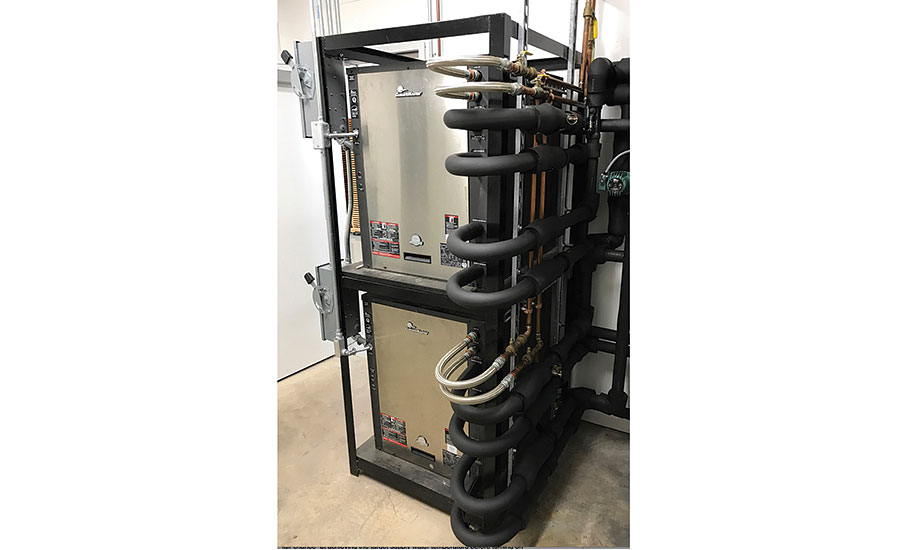
Figure 3.
If the heat pumps will supply chilled water, be sure all the piping is insulated and that the insulation is vapor-sealed. Take the time to carefully fit and trim the insulation around valves and circulator volutes.
THE BRAINS
There are several multiple-boiler controllers available that can be used to stage multiple water-to-water heat pumps.
The base staging operation is achieving and maintaining some target supply water temperature to the distribution system. Most of those controllers can also reduce the required supply-water temperature under partial-load conditions using outdoor reset. This allows the heat pumps to operate close to the minimum temperature needed to maintain space air temperature and keeps their COPs as high as possible.
As heating loads decrease, the run time of on/off heat pumps also decreases. Be careful not to create conditions that cause heat pumps to short-cycle. If necessary, use a buffer tank in place of the hydraulic separator to add mass to the system. Keep the on/off temperature differential for the heat pumps as wide as practical without sacrificing significant changes in COP or interior comfort. Make use of time delays between stage activations to ensure that each heat pump has a fair chance of achieving the target supply water temperature before turning on another stage.
When all the heat pumps are identical, the staging controller can be set to periodically rotate their operating order. This helps keep the total operating hours balanced between the heat pumps.
BOILER BACKUP
The piping arrangements shown in Figures 1 or 2 could also include an auxiliary boiler as a heating stage. Figure 4 shows a modification of the piping from Figure 2 that includes a boiler.
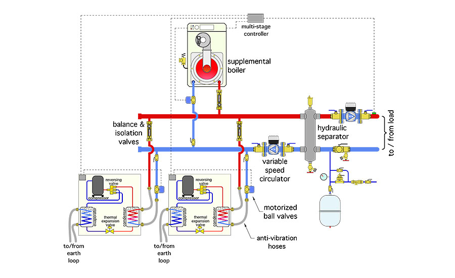
Figure 4.
If the boiler is only intended as a backup in case the heat pumps cannot collectively maintain the required supply water temperature, the control system needs to be configured to treat the boiler as a fixed “lag” stage. It should only fire the boiler after all the heat-pump stages have been activated but have collectively been unable maintain the necessary target supply-water temperature.
WHAT ABOUT THE EARTH-LOOP PIPING?
Many of you recognize that these same piping techniques could be applied to the earth-loop side of the multiple-heat-pump system. A single variable-speed circulator could regulate flow through the earth loop depending upon how many heat pumps are operating.
The evaporator side of each heat pump would be equipped with a motorized valve and balance valve. However, the control criteria for the circulator would not necessarily be constant ∆P. We’ll discuss the possibilities in a future column.
May you and your family have a blessed Christmas and Happy New Year.
To read Siegenthaler’s article: “How to pipe multiple water-to-water heat pumps” in pdf form, please see here.
Looking for a reprint of this article?
From high-res PDFs to custom plaques, order your copy today!


