Level-headed
The Glitch: Can you identify, describe, and propose a fix for several problems that are likely to develop with this system?
The Glitch:
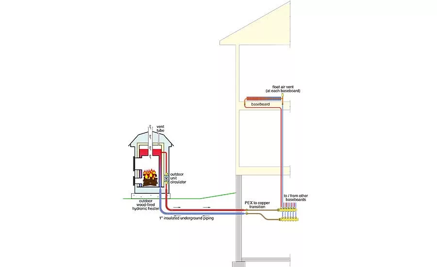
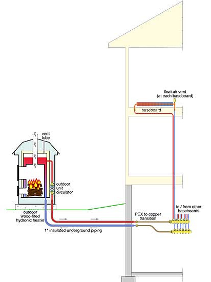
An unpressurized outdoor wood-fired heater rated at 150,000 Btu/h output, is installed to supply heat to fin-tube baseboard install in a two-story home as shown in the drawing below. The outdoor heater has its own 1/12-hp cast-iron circulator. Heated water is carried through 1” insulated underground PEX tubing from the outdoor unit to the house, which is about 150’ away. The 1” PEX tubing passes through the foundation wall and transitions straight into 1” copper tubing. From there, the system divides the flow up into several ½” PEX homerun circuits serving several baseboards in the house. Each baseboard has a float type air vent teed to its return end to eliminate air at the system's high points.
Can you identify, describe, and propose a fix for several problems that are likely to develop with this system?
The Glitch: Can you identify, describe, and propose a fix for several problems that are likely to develop with this system?
The Fix:
Several problems are going to show up very quickly. Others will show up as the system ages.
-
The water level in the outdoor wood burner establishes the 0 gauge pressure location in this system. Although the circulator might, when it’s operating, be able to push the water up and over the high point of the system, the water is going to reverse this height gain as soon as the circulator turns off. Under that condition, there will be negative pressure in any piping above the water level of the outdoor unit. The strongest negative pressure will be at the high point, right where a float type air vent is located. That vent will allow air to enter the system just like a vacuum breaker. The water will eventually drop to the same level as in the outdoor wood burner. When the circulator starts up again this process of filling the system only to have it drain itself when the circulator turns off will repeat. There will of course be air noises in the piping every time it fills and drains. Some diehard wood heating types might tolerate this, most people would not.
-
When the underground PEX tubing heats up it’s going to expand. A long length of PEX tubing routed through non-bonding insulation sleeving, will expand several inches in length when heated from ground temperature to perhaps 180° F. That expanding tubing is going to push, and push hard, against anything that restrains its movement. Without a suitable expansion compensation scheme, that developed stress could bend and kink copper tubing (I’ve seen it happen). Always provide an expansion compensation detail capable of absorbing several inches of movement when long lengths of unrestrained PEX tubing are connected to rigid piping.
-
The glitch drawing above is an “open” hydronic system. Oxygen will be absorbed into the water in the outdoor heater through its vent tube. Oxygen plus steel equals corrosion. It may be possible to suppress that corrosion if the water is properly treated with an oxygen scavenging additive and the additive level is periodically checked and maintained. If not, the cast iron circulator and other ferrous metal components are going to eventually fail. I don’t know of any circulator manufacture that warrants a cast iron circulator in an open loop hydronic system.
-
A 150,000 Btu/h heat source needs about 15 gpm of flow to operate at its rated capacity with a nominal 20° temperature differential. Do the math on moving 15 gpm water flow through 300’ of 1” PEX tubing (and for simplicity ignore the additional head loss of the distribution circuits, baseboard, fittings, valves, or other devices in the circuit), and you’ll find that a 1/12-hp circulator is not even close to supplying the necessary head. The 300’ of 1” underground PEX itself creates about 66’ of head loss at 15 gpm. It’s going to take a much larger, more powerful and more expensive circulator to achieve the desired flow. It’s even possible that the flow created by the 1/12-hp circulator will not be able to lift the water through the elevated distribution circuits, and thus the system will be air bound from the beginning.
The drawing below shows ways to correct these problems:
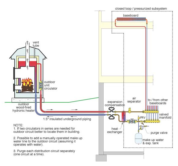
The Fix: This drawing shows ways to correct these problems.
-
Start by separating the “open” outdoor wood burner and underground tubing from a “closed” hydronic distribution system using a generously sized stainless steel heat exchanger. This eliminates the likely air binding and “drainback” issues associated with the open system.
-
Use stainless steel rather than cast iron circulators in the open portion of the system.
-
Install adequate expansion compensation between the PEX tubing and copper tubing.
-
Use two appropriately-sized “high head” circulators in a close-couple series arrangement to get the flow rate through the wood burner where it needs to be. Better yet, use 1.25” or even 1.5” PEX to handle the long distance underground circuit at 15 gpm with much lower head loss (about 12’ if 1.5” PEX was used). The higher cost of the larger tubing will eventually be recovered in the lower installation and operating costs associated with a much smaller circulator.
-
Add the usual trim to the closed loop subsystem: make-up water, expansion tank, air separator, purging valve, and pressure relief valve.
-
Eliminate the float-type air vents at the top of each branch circuit. A simple manual vent could be installed if desired. However, a good circuit-by-circuit forced water purging using the valved manifold station should be able to clear all the bulk air from the system. The microbubble air separator will clean up the dissolved gases over a few operating cycles.
Check out Level-headed in pdf form.
Looking for a reprint of this article?
From high-res PDFs to custom plaques, order your copy today!


