Larger than necessary
You’re probably oversizing expansion tanks in low-temperature systems.

All closed-loop hydronic radiant heating systems require an expansion tank to accommodate the increased volume of the heated fluid. The usual sizing method for expansion tanks determines the volume of the system’s fluid when the system is at it highest temperature relative to its volume when cold. The expansion tank volume is then calculated to accept the change in fluid volume without letting system pressure climb to the point that the pressure relief valve opens.
Step 1. Estimate the system’s fluid volume (not including any allowance for an expansion tank). Use the table in Figure 1 to estimate the volume contained in the system piping.
You’ll also need to look up the fluid volume contained in the system’s heat source. Most boiler manufacturers provide this data in their technical literature.
Add the tubing volume to that of the heat source and any other system components (buffer tank, heat exchangers, etc.) and call the total estimated system volume Vs.
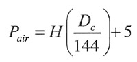
Step 2. Use Formula 1 to determine the air-side pressure required in the expansion tank to ensure the diaphragm is fully expanded against the tank shell when the fluid in the system is cold.
 Where:
Formula 1 can be used for systems containing either water or antifreeze solutions. It requires the density of the “cold” fluid used to fill the system. For water, use a value of 62.4 lb./cubic ft. For other fluids, look up their density at 60º F in manufacturers’ literature.
The number 5 at the end of Formula 1 allows for 5 psi of static pressure at the top of the piping system. This helps push air out through vents, as well as to suppress vapor pocket formation in high-temperature systems.
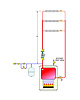
The value H in Formula 1 is the vertical distance from the inlet of the expansion tank to the top of the piping system (see Figure 2). The greater this height is, the greater the static pressure on the tank and the higher the air-side pressurization required to ensure the diaphragm remains fully expanded when the system is filled.
 Adjust the air pressure in
the diaphragm to the calculated value before you add fluid to the system. This
ensures that the diaphragm will not be partially compressed when the system is
filled, reducing the acceptance volume of the tank when it’s needed (e.g., when
the fluid starts to heat up).
Adjust the air pressure in
the diaphragm to the calculated value before you add fluid to the system. This
ensures that the diaphragm will not be partially compressed when the system is
filled, reducing the acceptance volume of the tank when it’s needed (e.g., when
the fluid starts to heat up).
Step 3. Calculate the required minimum expansion tank volume using Formula 2.
 Where:
The volume of the system (Vs) was found in Step 1. The air-side pressurization (Pa) was found in Step 2, as was the density of the fluid when the system is filled (Dc). The pressure relief valve setting (PRV) on most residential and light commercial systems is 30 psi.
All that’s left is to look up the density of the fluid when the system is at maximum temperature. This can be found using the graph in Figure 3 for water as well as two concentrations of propylene glycol.
For example, assume the top of a piping system is 20 ft. above the expansion tank connection. The system is filled with water at 60º. Based on the amount of piping and boiler volume, it’s estimated that the system contains 22 gal. of water. The boiler is equipped with a 30 psi relief valve. The maximum operating temperature of the system will be 200º. What’s the minimum expansion tank volume required?
Start by calculating the air-side pressurization using Formula 1:
 From
Figure 3, the density of water at 200º F is 60.07 lb./ft3. Putting the numbers
in Formula 2 yields:
From
Figure 3, the density of water at 200º F is 60.07 lb./ft3. Putting the numbers
in Formula 2 yields:
Remember, this is the minimum expansion tank volume required for this system. Using a larger volume tank is fine. An oversized expansion tank reduces variations in system pressure between its temperature extremes, albeit at higher cost.

Now consider a large radiant floor-heating system supplied by a conventional boiler. Let’s say the water leaving the boiler is 180º at design load conditions. Some of this water mixes with much cooler water returning from the floor circuits to produce a mixed supply temperature of 110º.
Obviously the water in the floor-heating circuits is significantly cooler than the water in the boiler and will not expand as much as the latter. Furthermore, the majority of the fluid volume in many floor-heating systems is contained in the floor circuits rather than the boiler and near-boiler piping.
Imagine a facility with a 300,000 Btu/hr. radiant panel system having a conventional boiler with a volume of 35 gal., some near-boiler piping with a volume of 4.5 gal. and 9,500 ft. of 5/8 in. PEX tubing in the floor slab. At design load, the water in the boiler and near-boiler piping reaches 180º, but the water in the radiant panel circuit reaches only 110º. The volume in the floor circuits is approximately 132 gal. That’s 77% of the total system volume. Assume the calculated air-side pressurization of the expansion tank is 12 psi and the system has a 30 psi relief valve.
 If we used Formula 2 to
size the expansion tank for this system, assuming all the fluid reaches the
same temperature as the boiler, the minimum expansion tank volume would be 16.5
gal.
If we used Formula 2 to
size the expansion tank for this system, assuming all the fluid reaches the
same temperature as the boiler, the minimum expansion tank volume would be 16.5
gal.
Compare this to a situation in which two hypothetical expansion tanks are sized: One for the fluid in the boiler and near-boiler piping that reaches 180º, and another for the fluid in the radiant panel circuits that reaches 110º at design load.
For the fluid volume that reaches 180º, the minimum expansion tank volume is:
 For the fluid volume that
reaches 110º, the minimum expansion tank volume is:
For the fluid volume that
reaches 110º, the minimum expansion tank volume is:
Now imagine these two hypothetical expansion tanks being combined into a single tank having a total volume of 3.8 + 4.2 = 8.0 gallons (as illustrated in Figure 4). This is about half the expansion tank volume calculated with the previous procedure that would assume all water in the system reaches 180º at design load.
Even this modified sizing procedure is conservative because it ignores the temperature drop of the fluid in the floor circuits and near-boiler piping when the system is operating. This temperature drop tends to lower the average fluid temperature and hence reduce the total expansion volume.

Using the first procedure, the required minimum expansion tank volume would have been 223 gal. Using the corrected procedure, the required minimum expansion tank volume was 89 gal. The savings realized using the smaller expansion tank was substantial.
For those of you who design large commercial floor-heating or snow-melting systems, the difference in the expansion tank volumes determined by these two procedures can be substantial. In some jobs, the modified calculation procedure could make the difference between an expansion tank that hangs below the air separator vs. one that’s floor-mounted. The latter being one more piece of equipment requiring floor space in the mechanical room.
Also keep in mind that glycol-based antifreeze solutions expand more than water as they change in temperature. The difference is further increased in the calculated expansion tank volumes. This is especially relevant when designing large snow-melting systems.
Although there is nothing technically wrong with oversizing expansion tanks, it certainly increases system cost. Good designers evaluate the alternatives using accurate procedures, then make an informed decision. The modified expansion tank sizing method we’ve discussed is a tool that lets you refine expansion tank sizes for systems having lower-temperature distribution systems. Use it when appropriate.
Figure 1. Chart.
All closed-loop hydronic radiant heating systems require an expansion tank to accommodate the increased volume of the heated fluid. The usual sizing method for expansion tanks determines the volume of the system’s fluid when the system is at it highest temperature relative to its volume when cold. The expansion tank volume is then calculated to accept the change in fluid volume without letting system pressure climb to the point that the pressure relief valve opens.
Formula 1
Classic sizing
Here’s a quick review of the classic sizing procedure for a diaphragm-type expansion tank in any type of closed-loop hydronic heating system.Step 1. Estimate the system’s fluid volume (not including any allowance for an expansion tank). Use the table in Figure 1 to estimate the volume contained in the system piping.
You’ll also need to look up the fluid volume contained in the system’s heat source. Most boiler manufacturers provide this data in their technical literature.
Add the tubing volume to that of the heat source and any other system components (buffer tank, heat exchangers, etc.) and call the total estimated system volume Vs.
Step 2. Use Formula 1 to determine the air-side pressure required in the expansion tank to ensure the diaphragm is fully expanded against the tank shell when the fluid in the system is cold.
Figure 2.
- Pair = the proper air-side pressure, before adding water to the
system (psi)
H = the height of liquid in the system above the inlet to the expansion tank (ft.)
Dc = the density of the system fluid at its initial (cold) fill temperature (lb./cubic ft.)
5 = an allowance for 5 psi static pressure at the top of the system.
Formula 1 can be used for systems containing either water or antifreeze solutions. It requires the density of the “cold” fluid used to fill the system. For water, use a value of 62.4 lb./cubic ft. For other fluids, look up their density at 60º F in manufacturers’ literature.
The number 5 at the end of Formula 1 allows for 5 psi of static pressure at the top of the piping system. This helps push air out through vents, as well as to suppress vapor pocket formation in high-temperature systems.
The value H in Formula 1 is the vertical distance from the inlet of the expansion tank to the top of the piping system (see Figure 2). The greater this height is, the greater the static pressure on the tank and the higher the air-side pressurization required to ensure the diaphragm remains fully expanded when the system is filled.
Formula 2
Step 3. Calculate the required minimum expansion tank volume using Formula 2.
- Vt = the required minimum volume of the expansion tank
(gal.)
Vs = the system volume (gal.)
PRV = the pressure at which the pressure relief valve opens (psi)
Pa = the correct air-side pressure (psi)
Dh = the density of the system fluid at its final (hot) temperature (lb./cubic ft.)
Dc = the density of the system fluid at its initial (cold) fill temperature (lb./cubic ft.)
The volume of the system (Vs) was found in Step 1. The air-side pressurization (Pa) was found in Step 2, as was the density of the fluid when the system is filled (Dc). The pressure relief valve setting (PRV) on most residential and light commercial systems is 30 psi.
All that’s left is to look up the density of the fluid when the system is at maximum temperature. This can be found using the graph in Figure 3 for water as well as two concentrations of propylene glycol.
For example, assume the top of a piping system is 20 ft. above the expansion tank connection. The system is filled with water at 60º. Based on the amount of piping and boiler volume, it’s estimated that the system contains 22 gal. of water. The boiler is equipped with a 30 psi relief valve. The maximum operating temperature of the system will be 200º. What’s the minimum expansion tank volume required?
Start by calculating the air-side pressurization using Formula 1:
Remember, this is the minimum expansion tank volume required for this system. Using a larger volume tank is fine. An oversized expansion tank reduces variations in system pressure between its temperature extremes, albeit at higher cost.
Figure 3.
Very conservative
The above procedure sizes the expansion tank so the maximum system pressure is 5 psi lower than the relief valve setting, assuming all the system fluid reaches the maximum temperature at the same time, presumably under design load conditions. After giving this some thought, you will realize such a situation is not possible. The water temperature supplied by the heat source must drop if the system is releasing heat.Now consider a large radiant floor-heating system supplied by a conventional boiler. Let’s say the water leaving the boiler is 180º at design load conditions. Some of this water mixes with much cooler water returning from the floor circuits to produce a mixed supply temperature of 110º.
Obviously the water in the floor-heating circuits is significantly cooler than the water in the boiler and will not expand as much as the latter. Furthermore, the majority of the fluid volume in many floor-heating systems is contained in the floor circuits rather than the boiler and near-boiler piping.
Imagine a facility with a 300,000 Btu/hr. radiant panel system having a conventional boiler with a volume of 35 gal., some near-boiler piping with a volume of 4.5 gal. and 9,500 ft. of 5/8 in. PEX tubing in the floor slab. At design load, the water in the boiler and near-boiler piping reaches 180º, but the water in the radiant panel circuit reaches only 110º. The volume in the floor circuits is approximately 132 gal. That’s 77% of the total system volume. Assume the calculated air-side pressurization of the expansion tank is 12 psi and the system has a 30 psi relief valve.
Compare this to a situation in which two hypothetical expansion tanks are sized: One for the fluid in the boiler and near-boiler piping that reaches 180º, and another for the fluid in the radiant panel circuits that reaches 110º at design load.
For the fluid volume that reaches 180º, the minimum expansion tank volume is:
Now imagine these two hypothetical expansion tanks being combined into a single tank having a total volume of 3.8 + 4.2 = 8.0 gallons (as illustrated in Figure 4). This is about half the expansion tank volume calculated with the previous procedure that would assume all water in the system reaches 180º at design load.
Even this modified sizing procedure is conservative because it ignores the temperature drop of the fluid in the floor circuits and near-boiler piping when the system is operating. This temperature drop tends to lower the average fluid temperature and hence reduce the total expansion volume.
Figure 4.
Where does this matter?
A few years ago I designed a radiant floor-heating system containing 21 miles of 3/4 in. PEX tubing. The floor circuits held approximately 2,100 gal. of fluid. The boilers and near-boiler piping held about 225 gal. of fluid. And 90% of the system’s volume was in the floor circuits.Using the first procedure, the required minimum expansion tank volume would have been 223 gal. Using the corrected procedure, the required minimum expansion tank volume was 89 gal. The savings realized using the smaller expansion tank was substantial.
For those of you who design large commercial floor-heating or snow-melting systems, the difference in the expansion tank volumes determined by these two procedures can be substantial. In some jobs, the modified calculation procedure could make the difference between an expansion tank that hangs below the air separator vs. one that’s floor-mounted. The latter being one more piece of equipment requiring floor space in the mechanical room.
Also keep in mind that glycol-based antifreeze solutions expand more than water as they change in temperature. The difference is further increased in the calculated expansion tank volumes. This is especially relevant when designing large snow-melting systems.
Although there is nothing technically wrong with oversizing expansion tanks, it certainly increases system cost. Good designers evaluate the alternatives using accurate procedures, then make an informed decision. The modified expansion tank sizing method we’ve discussed is a tool that lets you refine expansion tank sizes for systems having lower-temperature distribution systems. Use it when appropriate.
Links
Looking for a reprint of this article?
From high-res PDFs to custom plaques, order your copy today!


