From Dumb Curves To Smart Areas
John Siegenthaler, PE
If any of this sounds unfamiliar, please take the time to review the January 2008 Hydronics Workshop column titled Whatever’s On the Truck (free registration is required to view our Archives section). It gives you the basics of how these curves are constructed and used to properly match a circulator to a piping system.
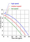
Any fixed-speed circulator has one pump curve. A circulator with multiple operating speeds will have a different pump curve for each speed. A good example is the common three-speed, wet-rotor circulators now available from several manufacturers. An example is shown in Figure 1.
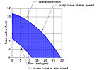
So, what would the situation look like if the circulator had four, five or even 10 speeds? Well, just add a new curve for each speed. Each time the speed decreases, the curve shifts downward and to the left. Now imagine a circulator with an “infinite” number of speeds. If you drew perhaps 50 of the possible pump curves, you might get something like what’s shown in Figure 2.
The highest curve represents the circulator’s performance at maximum speed. The lowest curve represents its performance at minimum operating speed. All the blue area in between these bounding curves represents remaining possible pump curves at other speeds. I’ll refer to the area between the highest and lowest curves as the “operating region” of the variable-speed circulator. By varying its speed, the circulator is theoretically capable of operating at any point within this region.
Trimming The Edges
Although some pump curves extend all the way from the vertical (head) axis down to the horizontal (flow) axis, there are reasons not to operate such circulators at or near the extremes of these curves.To begin with, the wire-to-water efficiency of any circulator drops off significantly as its operating point shifts from the center of the pump curve toward either axis. That efficiency, which involves the multiplication of flow rate and differential pressure, becomes zero at either axis. It’s a poor practice to operate a circulator in the single-digit efficiency range by creating situations that force it to run near the extremes of the pump curve.
Next, differential pressure across the circulator increases with head. The higher the differential pressure across the circulator, the greater the axial thrust on the impeller shaft and its bushings or bearings. Over time, sustained high differential pressure increases wear on these bushings or bearings.
Finally, when a circulator operates very low on its pump curve, it is more prone to cavitation. This is partly due to head loss that occurs as flow passes from the inlet flange of the volute to the eye of the impeller. The higher the flow rate, the higher this head loss. Some circulators are also subject to motor overload if operated at very high flow rates and low differential pressure.
For these reasons, you’ll often see that pump curves for larger circulators don’t run out to either axis. They end at the maximum head and flow rate combinations beyond which the manufacturer does not want the pump operating. The same is true for variable-speed circulators as depicted in Figure 3.

Adding Some Smarts
Any wet-rotor circulator with a PSC (permanent split capacitor) motor can operate over a wide range of speeds. Doing so requires a controller that varies the frequency of the AC signal sent to the circulator’s motor. The controller’s AC power wave to the circulator is usually based on some type of operating algorithm. A standard wet-rotor circulator operated by a variable-speed injection mixing controller is a good example.One could describe a standard PSC circulator operated by such a controller as “dumb,” because it doesn’t contain the necessary operating logic and speed control circuitry to operate as a stand-alone entity. Instead, it’s completely subservient to the AC signal it receives from a “smart” controller. Another example of a “dumb” variable-speed circulator is one that does contain the AC speed-control circuitry, but responds to an external 0-10 volt DC control signal. In this case, whatever varies the 0-10 volt DC signal holds full control over the circulator’s speed.
In recent years, so-called “smart circulators” have shown up in the residential hydronics market. Until a couple of years ago they were primarily wet-rotor circulators with PSC motors “enhanced” with built-in electronics that provided both the AC drive circuitry and control logic for operating modes such as temperature setpoint control, differential temperature control and variable-speed injection mixing. In essence, the “smarts” that used to be housed externally to the circulator became onboard components.
These circulators can be used for specialized tasks in hydronic systems such as boiler protection, maintaining a set temperature drop around a primary loop and mixing. Still, underneath the added smarts, they are wet-rotor circulators with PSC motors. Although some energy savings will result from reduced operating speed, the wire-to-water efficiency of such circulators is quite low compared with what’s possible with newer technology.

From PSC To ECM
Another category of smart circulators is based on electronically commutated motor (ECM) technology. These motors, which are sometimes also called “brushless DC” motors, are very different from their PSC counterparts. The rotor in an ECM motor contains powerful and permanent neodymium magnets rather than wire windings. These magnets are sealed away from system fluid within a stainless-steel rotor can, and respond to the magnetic forces created by electromagnetic poles in the stator (see Figure 4).A microprocessor controller within the circulator reverses the polarity of these stator poles in milliseconds, allowing the rotor to be continually torqued in the direction of rotation. The faster the stator poles reverse their polarity, the faster the rotor spins.
Think of the stator poles as four energetic kids pushing and pulling on a merry-go-round to keep it spinning. Each kid grabs the approaching bar on the merry-go-round, pulls on it for a fraction of a second and, as soon as it passes by, pushes on it for another fraction of a second.
ECM circulators also provide approximately four times more starting torque compared to a PSC-based wet-rotor circulator of comparable size. With this technology, you can pretty much forget about stuck rotors after a few months of inactivity.
-sm.jpg)
Multiple Personalities
Just as a computer can run different software, the microprocessor in an ECM-based circulator can execute many different instruction sets. This allows the circulator to take on different “personalities,” depending on how it’s applied. In one system, the circulator can operate as a constant differential pressure device; in another system, it can operate as a proportional differential pressure device. In still another installation it might serve as a variable-speed mixing pump. The possibilities are far-reaching, and allow a single circulator to potentially replace several first-generation “smart pumps” that have only one or two operating modes.Figure 5 shows the operating region of a smart pump when operating in a constant differential pressure mode. The installer sets the circulator for the desired head at design load conditions (when all zone valves are open). When one or more zone valves close, the circulator internally senses a momentary increase in differential pressure and quickly responds by reducing motor speed to cancel out the “attempted” change in differential pressure. This allows the operating point (e.g., the intersection between the pump curve and the system head loss curve) to track along a horizontal line. Constant head means constant differential pressure.
When a given zone valve closes, the other zones don’t “feel” any change in differential pressure and, thus, their flow rates remain the same. The net effect is “cruise control” for differential pressure. It’s what our industry has approximated in the past using differential pressure bypass valves. However, with smart circulators we no longer need bypass valves and we get significant electrical energy savings to boot.
-sm.jpg)
Sometimes you’ll see graphs for variable-speed circulators that show overlapping operating regions for different model circulators. In such cases, select the circulator with the upper-end curve that is reasonably close to and a bit above the system operating point (flow rate and head at design load conditions).
The wire-to-water efficiency of any circulator and at any speed remains highest near the center of the pump curve. Thus, it’s best to select a circulator where the operating point, especially during higher speed operation, falls near the center of the pump curve. When a variable-speed circulator operates based on constant differential pressure or proportional differential pressure mode, the operating point will shift toward the left of the operating region as circulator speed is reduced. This does lower efficiency. However, that reduced efficiency corresponds to lower operating wattage, and doesn’t play as great a role in determining total electrical energy use on a seasonal basis.
Variable-speed circulators will steadily gain market over their fixed-speed predecessors just as mod/con boilers have gained market share over on/off boilers. Their improved wire-to-water efficiency combined with multiple operating mode capability makes them one of the “greenest” design options currently available to hydronic professionals.
Customers benefit from lower operating cost. Installers benefit from versatility and wholesalers benefit from less SKUs to cover a range of applications. As of this writing, two major circulator manufacturers have variable-speed smart circulators available in the North American market. Additional offerings from other companies are no doubt waiting in the wings. Get ready to apply them and reap the benefits.
Looking for a reprint of this article?
From high-res PDFs to custom plaques, order your copy today!


