
Setting Up a Failproof System with an Air-to-Water Heat Pump and Boiler
Many air-to-water heat pumps now include hydronic-side components and system-level controls, but installers still need a backup plan when those controls go down.

As more air-to-water heat pumps enter the U.S. market, successful installations depend on understanding internal components, system controls and heat pump offline operation.
There are at least 19 air-to-water heat pump suppliers currently in the US market. Some of them are based on designs developed in Europe or Asia. These heat pumps come from well-established markets and tend to be designed as more than just a “box” that produces heated or chilled fluid. In addition to their refrigeration systems, many of these heat pumps contain hydronic-side components that are more typically “field supplied” in North American systems. Examples include a circulator, expansion tank, pressure relief valve, and in some cases an electric flow-though booster heater.
Designers and installers need to know exactly what internal hydronic-side component are supplied within the heat pumps they choose to work with. They also need to know the performance ratings or limitations of those components.
For example, some air-to-water heat pumps are supplied with an internal expansion tank. The size of that tank determines how much volume the system can contain without the need of a supplemental expansion tank. Although typical values for maximum system volume without a supplemental tank are about 50 gallons, designers need to check this value for a specific heat pump model.
The same due diligence needs to be applied to internal pressure relief valves. Coming from outside the US, don’t assume that internal PRVs are rated at a typical 30 psi. A more typical rating is 2 to 3 bars (29.4 to 44.1 psi). These ratings may be fine when the heat pump is the only heat source in the system, but if the system contains another heat source, or just another PRV at some other location, that PRV will likely open first. It’s also worth checking to see if there are any applicable code requirements that may require a lower PRV rating compared to that of the internal PRV.
Some air-to-water heat pumps are supplied with internal circulators. The circulator might be able to provide flow through the entire system (e.g., direct-to-load configuration), or it may only be able to provide flow to a buffer tank or hydraulic separator. Designers need to know the net pump curve (e.g., head and flow curve available external to the heat pump) to assess if the circulator is suitable for the distribution system connected to the heat pump. Two or three zones of baseboard or fan-coils are likely with the ability of the internal circulator. However, an extensive radiant floor heating system, especially one using small 5/16” or 3/8” PEX tubing may have exceptionally high head requirements that are beyond the range of the internal circulator.
System Brain
In addition to hydronic-side components, many of these heat pumps are equipped with internal controls capable of managing both the heat pump’s refrigeration system and balance-of-system control functions. Examples include the ability to:
- Operate an auxiliary heat source
- Monitor the temperature of an indirect domestic water heater
- Prioritize a call for domestic water heating over space heating or cooling
- Redirect flow from heat pump to space heating or domestic water heating load
- Accept signals from zone thermostats, and operate zone circulators or zone valves.
- Modulate the output of a mod/con boiler using a 0-10 VDC output
- Automatically switch heating loads from heat pump to boiler based on outdoor temperature
- Automatically change the target leaving water temperature based on outdoor temperature
Manufacturers add this functionality to reduce the need for external controls, and minimize potential conflicts between the operating logic of the heat pump and the “unknown” operating logic of the balance of system connected to the heat pump.
Rerouting
One common system level control function is operating a 3-way motorized diverter valve to direct the heated water leaving the heat pump to either space heating or the coil of an indirect domestic water heater. Figure 1 shows a typical piping arrangement.
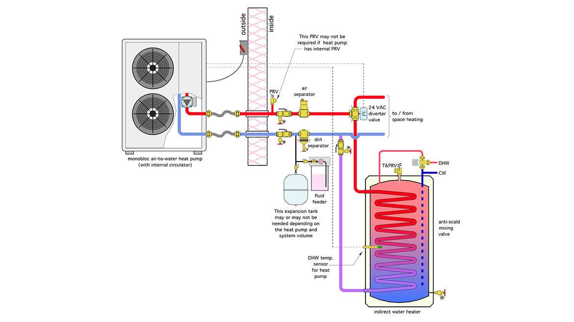
Figure 1 Diagram courtesy John Siegenthaler
The heat pump monitors the temperature of the indirect water heater using a thermistor sensor. When the tank needs heating the heat pump operates the 3-way diverter valve to direct flow from the heat pump to the tank’s coil heat exchanger. Once the tank is heated to its set temperature, the motorized valve reverses to direct flow to space heating. If both space heating and domestic water heating loads call simultaneously, most air-to-water heat pumps with “system level” control capability will prioritize the latter, allowing it to be the only load for a user-set period of time. If that time elapses the heat switch back to space heating.
This load sharing scenario then repeats until one of the two loads stops calling for heat. These heat pumps also change their target leaving temperature based on which load is calling for heat. Higher setpoint temperatures are used during domestic water heating. The target leaving water temperature for space heating is usually based on outdoor reset control.
Backup Plan
Many air-to-water heat pumps are combined with boilers. In retrofit projects, it’s likely an existing boiler, in new projects, it’s likely a mod/con boiler. The boiler can provide supplemental heat during very cold weather. It can also serve as a backup heat source should the heat pump become inoperable.
Figure 2 shows a typical piping arrangement where a mod/con boiler is combined with an air-to-water heat pump. The system also uses a 3-way motorized diverter valve to route flow to either space heating or domestic water heating.
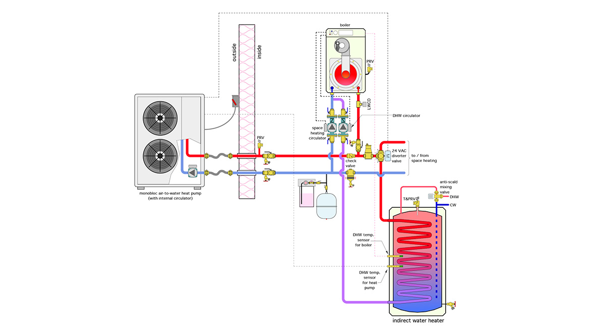
Figure 2 Diagram courtesy John Siegenthaler
The boiler is piped in parallel with the heat pump. This configuration assumes that the boiler has two line voltage circulator outputs. One circulator operates during space heating, the other operates when there’s a call for domestic water heating. Both circulators are equipped with internal check valves to prevent reverse flow.
Imagine a system that includes both a heat pump and a boiler as shown in figure 2. During normal operation the heat pump controls boiler operation as needed for either space heating or domestic water heating.
As fate would have it, a nearby lightning strike sends a high voltage spike into the house that “fries” something on the heat pump’s control board, but doesn't take out the boiler. If the heat pump is the only control path to operate the boiler and the 3-way diverter valve, and it’s now incapable of doing either, the system can’t provide space heating or DHW. This is not going to go over well with an owner who understands (or eventually learns) that the boiler is capable of operating, but can’t because it was wired through the heat pump.
This is where a simple “work around” is needed. It takes the form of a switch that the owner can operate that allows the boiler to provide both space heating and domestic water heating until the heat pump is repaired. Figure 3 shows one way to do this using a 4PDT switch and a simple 120 VAC relay.
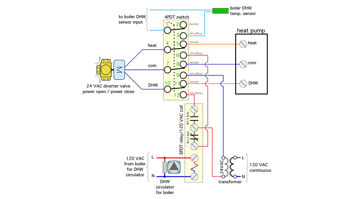
Figure 3 Schematic courtesy John Siegenthaler
The switch is a four pole / double throw (4PDT) configuration. It has 12 terminals. We’ve talked about the best way to wire such a switch in recent PMC&E columns.
This schematic assumes that the diverter valve’s actuator is 24VAC power open / power close. It uses a 24VAC input to one terminal to rotate the valve’s shaft to the space heating position. A 24 VAC input to another terminal rotates the valve to the DHW position. The third wire to the actuator is the common side of a separate 24 VAC transformer. That transformer is necessary, because the transformer in the heat pump is out of service.
Three of the four poles on the (4PDT) switch determine what supplies 24VAC to the diverter valve actuator. When the switch is in its “normal” position the voltage to operate the valve’s actuator comes from the heat pump. When the switch is in the “HP offline” position, the 24 VAC comes from a separate transformer.
The fourth terminal on the switch connects the boiler’s DHW tank sensor to its input terminals on the boiler. Remember — in normal mode — the heat pump’s DHW tank sensor is what controls the heat pump, and the boiler if needed, during DHW operation.
A small relay with a 120 VAC coil is used to switch the 24VAC input to the diverter valve between the space heating and DHW states. The relay’s coil is wired in parallel with the boiler’s DHW circulator. As soon as the boiler starts a call for domestic water heating, it energizes the DHW circulator, and the relay coil, which sends the necessary 24 VAC from a separate transformer to the motorized valve, putting it in the DHW portion.
If you use this circuit, be sure to mount the switch where it’s easily found within the mechanical room. Label both positions of the switch. I like the labels, “normal operation” and “heat pump offline operation.” Be sure to explain when and how the switch is to be used. Include a note on or adjacent to the switch telling the owner to turn off the breaker to the heat pump as a safety precaution, and then move the switch to heat pump offline position.
There are other possibilities for accomplishing the same goal of enabling boiler operation when the heat pump is down. The specific piping and controls will depend on the available outputs from the boiler. An example would be using the same circulator for both space heating and domestic water heating modes. This would need to be coordinated with the corresponding supply water temperatures from the boiler depending on its operating mode.
This relatively uncomplicated and inexpensive circuit will demonstrate your thoughtfulness in providing a way for the owner to get the boiler back in operation until the heat pump can be repaired. This switch probably wouldn’t be needed if a service technician is available, has all the necessary parts for the heat pump, and is only a few hours away from making the repair. However, given the pace at which these heat pumps are entering the market, there’s no guarantee that all possible replacement parts will be kept in immediately available stock. Instead, those parts might be several days (or more) away. That’s a long time for the home’s occupants to be without space heating and domestic hot water. Keep your customers warm - give them an easy way to keep the boiler operating if the heat pump is down for service. They’ll appreciate your forethought.
Looking for a reprint of this article?
From high-res PDFs to custom plaques, order your copy today!