
Renewable Heating Design | John Siegenthaler
An Open & Shut Case (Part 2)
How a reversible thermal storage system can integrate with heat sources and loads, using strategic piping, controls and temperature management.
Last month, we looked at a way to combine a non-pressurized thermal storage tank with a brazed plate stainless steel heat exchanger, two circulators and two motorized valves to create a reversible thermal storage system. That system is shown in figure 1.
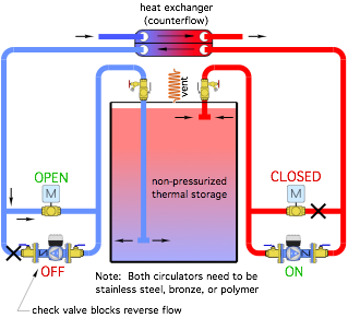
Figure 1 Image courtesy of John Siegenthaler.
Reversible flow is critically important for maintaining temperature stratification in the storage tank.
“Ins” & “Outs”
Figure 2 expands the reversible thermal storage subsystem to include a heat source (i.e., air-to-water heat pump, geothermal water-to-water heat pump, or an electric boiler), and a load.
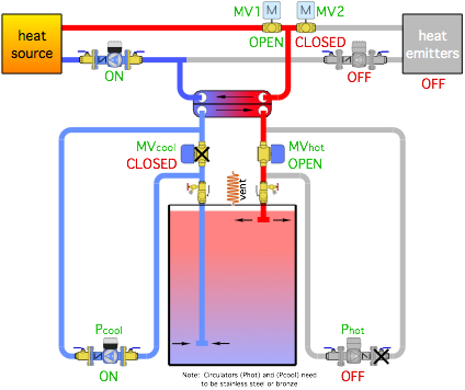
Figure 2 Image courtesy of John Siegenthaler.
Heat Source to Storage Mode
The operating mode shown in figure 2 enables the heat source to send heat to the thermal storage tank. The heat emitters are not operating. This mode would apply when time-of-use electrical rates are low, typically at night, on weekends and certain holidays.
Motorized ball valve (MV1) is open, and motorized ball valve (MV2) is closed. The latter forces all flow from the heat source into thermal storage. The circulators and valves below the heat exchanger create flow from the bottom of the thermal storage tank, through the heat exchanger (in counterflow to the heat source flow), and back to the upper portion of the thermal storage tank.
In addition to making the circuit through the upper portion of the heat exchanger a closed loop, the heat exchanger allows the fluid in the circuit containing the heat source to be an antifreeze solution. This is often needed when the heat source is a monobloc air-to-water heat pump.
Storage to Load Mode
Figure 3 shows the same piping, but in the mode where heat is sent from storage to the load.
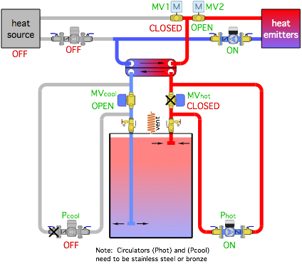
Figure 3 Image courtesy of John Siegenthaler.
Valve (MV1) is closed blocking flow through the heat source, which is off in this mode. Valve (MV2) is open and the distribution circulator is running. Hot water from thermal storage passes through the heat exchanger in counterflow transferring heat to the load.
The flow directions through both sides of the heat exchanger have reversed, but counterflow has been maintained. The flow directions into and out of the thermal storage tank have also reversed. Temperature stratification within the tank is maintained.
Direct to Load Mode
Figure 4 shows the mode where the heat source supplies the load without any involvement of thermal storage.
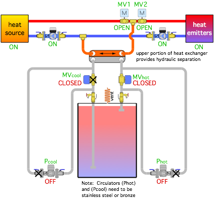
Figure 4 Image courtesy of John Siegenthaler.
This mode could be used if thermal storage is too cool to supply the load, or as a default if the thermal storage system is offline for service.
One of the unique benefits of this mode is that the upper portion of the heat exchanger provides hydraulic separation between the heat source circulator and the distribution circulator. However, to maximize this effect, the head loss through the upper portion of the heat exchanger combined with the head loss of the piping connecting it to the two tees ( e.g., the components shown in orange in figure 4) needs to be as low as possible. Fortunately, brazed plate heat exchangers can be sized for very low head loss.
Tempered Expectations
Consider this system combined with low water temperature heat emitters, such as certain types of floor heating. There will be times when the water in storage is too hot for the requirements (or limitations) of the heat emitters. Some type of supply temperature control is needed between storage and the heat emitters.
One way to provide this is to vary the speed of circulator (Phot). By varying the flow rate through the “hot” side of the heat exchanger, the water temperature leaving the “cool” side of the heat exchanger and supplied to the heat emitters can be regulated. This option is shown in figure 5.
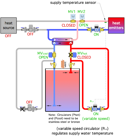
Figure 5 Image courtesy of John Siegenthaler.
The method used to control the speed circulator (Phot) depends on the circulator. Some stainless-steel ECM circulators are equipped with a 0-10 VDC input for speed control. Some also have a PWM (pulse wide modulation) input for speed control. Either of these inputs would have to be sourced from a separate controller that measures the water temperature supplied to the heat emitters and varies the output signal as needed to keep that temperature as close to a target value as possible. The target supply temperature could be a setpoint or based on outdoor reset. There are also circulators available that have onboard temperature control logic along with input terminals for a thermistor temperature sensor.
It would also be possible to change motorized valve (MV2) to a 3-way mixing valve, as shown in figure 6.
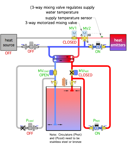
Figure 6 Image courtesy of John Siegenthaler.
Circulator (Phot) would operate at a fixed speed. The mixing valve would blend hot water from the upper side of the heat exchanger with cooler water returning from the heat emitters to achieve the target supply water temperature. When the heat source is charging storage, and there’s no demand for heat at the heat emitters, the “A” port of the mixing valve would be fully closed.
Divide & Conquer
Another possible mode is when the heat source is charging storage at the same time that some load exists. This could be handled by opening valve (MV1) and modulating flow through the 2-way valve (MV2) in figure 2. It could also be done by regulating hot water flow into the 3-way valve shown in figure 5. Controls would be needed to divide flow from the heat source between storage and the heat emitters. Given that maintaining comfort is likely the priority, the flow into storage would be limited until the load is satisfied. At that point all flow from the heat source would be directed into storage.
As discussed in part 1, non-pressurized storage systems have advantages and limitations. In applications where cost per gallon of storage is critical, or where it’s otherwise impractical to bring in one or more pressure-rated tanks, a non-pressurized tank combined with the piping and control concepts discussed represents a viable solution to leverage the combination of time-of-use electrical rates, heat pumps, and the unsurpassed comfort made possible by modern hydronics technology.
Looking for a reprint of this article?
From high-res PDFs to custom plaques, order your copy today!


.webp?height=200&t=1783240106&width=200 "An Open & Shut Case (part 1)")

