Renewable Heating Design | John Siegenthaler
How do North American and European hydronic systems differ?
I often compare hydronic systems designs that are common in North America with typical European equivalents. Sometimes those comparisons reveal details that would be beneficial in either market, but are not “traditional” in one market or the other.
One example is the use of a variable speed injection circulator as a mixing assembly in thousands of North American hydronic heating systems. I’ve yet to see this technique used in European system, where mixing is almost always done using 3-way or 4-way motorized mixing valves. Either approach can work, and they both have strengths and limitations. System designers who are familiar with both approaches are equipped to select the one that’s best suited to a specific situation.
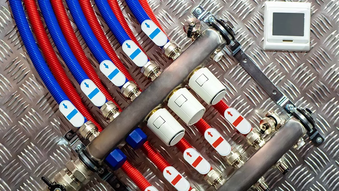
Another difference that has become apparent is the use of (or lack of) an expansion tank on residential geothermal earth loops. Schematics from Europe, such as the one in Figure 1, almost always show an expansion tank on the earth loop.

Figure 1. Courtesy of Caleffi S.p.a., click to enlarge.
Schematics for residential system from various North American sources typically do not show an expansion tank.
So, why the difference?
Some North American geothermal pros think that the HDPE piping used for geothermal earth loops has sufficient elasticity to absorb the fluid’s expansion during the cooling season. Arguably, there are likely thousands of geothermal heat pump systems installed in North America that apparently have operated acceptably based on this concept.
To the contrary, I’ve also had professionals from the geothermal heat pump industry ask me about what they called a “flat” loop condition. They describe it as a situation where the earth loop circulator(s) start making “swishing” sounds as the temperature of the loop increases during cooling mode operation. Although this sounds like a case in which air in the circuit was not fully purged when the system was commissioned, there’s an anomaly… The swishing sounds goes away - on their own - when the heat pump switches to heating operation.
Given these behaviors the swishing sounds are likely the result of gaseous cavitation within the circulator. This occurs when the absolute pressure at the eye of the circulator’s impeller drops low enough to allow dissolved air molecules (nitrogen, oxygen, etc.) to instantly come out of solution and form bubbles. It’s analogous to seeing bubbles form when the cap is popped off a bear bottle.
So, why is this happening in late summer and going away in winter?
It comes down to the volumetric expansion and contraction characteristic of both the fluid and the HDPE pipe. They are not the same…
During summer, when the earth loop fluid is warm, the internal volume of the HDPE pipe expands slightly faster than the volume of the fluid. This causes the loop pressure to drop.
During summer, when the earth loop fluid is warm, the internal volume of the HDPE pipe expands slightly faster than the volume of the fluid. This causes the loop pressure to drop. In a closed fluid-filled circuit, it doesn’t take much of this effect to bring the absolute pressure of the fluid below the saturation point for dissolved air molecules. Microbubbles develop at the eye of the circulator’s impeller, and hence the gaseous cavitation and swishing sounds.
During winter the earth loop fluid is cool. This causes both the pipe and fluid volume to contract. The internal volume of the pipe decreases slightly faster than the volume of the fluid. This causes an increase in loop pressure. Although most geothermal loops can handle this pressure increase it does increase the potential for leaks, especially at threads joints.
Add a tank: Water, or mixtures of water and antifreeze are - for all practical purposes - incompressible fluids. Small changes in temperature can cause large changes in pressure when an incompressible fluid completely fills a closed container. A closed hydronic circuit is a closed container. Although the pressure changes will be smaller for HDPE pipe due to its elasticity compared to that of metal pipe, it still makes sense to reduce the pressure fluctuations when possible. Including an expansion tank in the circuit is the simplest way to do this.
To size the expansion tank, it’s necessary to know how much fluid volume will be exiting the tank when the earth loop circulator reaches its maximum operating temperature in cooling mode. It’s also necessary to know how much fluid will enter the tank when the fluid reaches its lowest operating temperature during heating mode. These two volumes are not necessarily the same. Whichever condition involves the greater volume change in the expansion tank will set the constraining condition for sizing.
The volume of fluid entering the tank during heating mode operation can be calculated using formula 1:

Formula 1. Courtesy of John Siegenthaler
Where:
Vin = volume of fluid flowing into of expansion tank (gallons)
Vloop = total volume of earth loop when filled and purged (gallons)
a = coefficient of linear expansion of earth loop piping (in/in/ºF)
∆T = absolute value (e.g., always a positive number) of temperature change of loop (ºF)
Dfill = density of fluid when loop is filled and purged (lb/ft3)
Dlow = density of fluid when loop is at minimum temperature (lb/ft3)
The volume of fluid existing in the tank during cooling mode operation can be calculated using formula 2.

Formula 2. Courtesy of John Siegenthaler
Vout = volume of fluid flowing out of expansion tank (gallons)
Vloop = total volume of earth loop when filled and purged (gallons)
a = coefficient of linear expansion of earth loop piping (in/in/ºF)
∆T = absolute value (e.g., always a positive number) of temperature change of loop (ºF)
Dfill = density of fluid when loop is filled and purged (lb/ft3)
Dhigh = density of fluid when loop is at maximum temperature (lb/ft3)
Some of the quantities needed for formulas 1 and 2 are the same. The three fluid densities can usually be referenced from the same source, such as the graph in figure 2, which shows how the density of a 30% solution of propylene glycol varies with temperature.

Figure 2. Courtesy of John Siegenthaler
The volume of the HDPE piping portion of the earth loop can be found based on the length and size(s) of the pipe used. Figure 3 gives these volumes for smaller sizes of SDR-11 HDPE pipe.
| tubing | volume (gallons / 100 feet) |
| ¾" SDR-11 HDPE tubing | 3.01 gal/100 ft |
| 1" SDR-11 HDPE tubing | 4.72 gal/100 ft |
| 1.25" SDR-11 HDPE tubing | 7.53 gal/100 ft |
| 1.5" SDR-11 HDPE tubing | 9.86 gal/100 ft |
| 2" SDR-11 HDPE tubing | 15.41 gal/100 ft |
Figure 3
The coefficient of expansion for HDPE pipe is 0.0001 in/in/ºF
Here’s an example: Assume a closed earth loop circuit has a volume of 256 gallons. Determine the amount of fluid the enters the expansion tank when the loop temperature drops from 50 to 30 ºF. Also determine the amount of fluid that exits the tank when the loop temperature is raised from 50 to 90 ºF.
Use formula 1 to find the volume of fluid that enters the tank:

Courtesy of John Siegenthaler
Use formula 2 to determine the volume of fluid the exits the tank.

Courtesy of John Siegenthaler
Figure 4 illustrates how these earth loop temperature changes would affect the volume in an expansion tank.

Figure 4. Courtesy of John Siegenthaler
The calculations show that the greater fluid volume change occurs when the heat pump is operating in cooling mode and thus increasing the temperature of the earth loop.
Sizing the tank: The 0.86 gallon volume change becomes one of three constraining conditions for sizing the expansion tank.
The second constraint is the allowable pressure drop within the air side of the tank when 0.86 gallons of fluid exit. That change will be from some initial pressure (Pi) to some final press (Pf). For the sake of a calculation, assume that the air pressure in the tank will drop from 20 to 10 psi as 0.86 gallons of fluid exits.
The final constraint is how much fluid volume is in the expansion tank prior to the temperature change. A reasonable assumption is that half the tank shell volume contains fluid and the other half contains compressed air.
One final assumption that simplifies the calculations is that the temperature change of the captive air inside the expansion tank is minimal and thus can be excluded from the calculations. This is reasonable if the tank is located a few feet away from the loop and the tank’s shell temperature is mostly dominated by a stable surrounding air temperature.
The three constraints and one assumption allow Boyle’s law for perfect gas (e.g., the air in the expansion tank) to be set up and solved for the required tank shell volume, as shown in formula 3.

Formula 3. Courtesy of John Siegenthaler
Where:
Vtank = required volume of expansion tank (gallons)
Vout = volume of fluid leaving tank as loop heats to max operating temperature (gallons)
Pi = initial air side pressure in tank (when loop is charged) (psig)
Pf = final air side pressure in tank (when loop is at max. temperature) (psig)

Courtesy of John Siegenthaler
This result indicates that an expansion tank of 4.25 gallons total shell volume initially at 20 psi air side pressure and half-filled with fluid will allow the system loop pressure to drop from 20 to 10 psi after 0.86 gallons of fluid exit the tank, which corresponds to the earth loop and fluid reaching a maximum temperature of 90 ºF.
The calculated tank shell volume of 4.25 gallons represents the minimum volume that would allow the assumed pressure changes for this particular system. Conservative design practice would be to specify a tank with a slightly larger shell volume. Doing so would further reduce the seasonal pressure changes in the earth loop. Slightly oversizing the tank also allows it to hold some extra fluid in reserve to replace any air captured and released from the earth loop by a microbubble air separator. This reduces the possibility of having to revisit the site to add small amounts of fluid after the air separator has done its job.
Finally, it’s important to properly support any expansion tank that hangs from its top connection. Figure 5 shows one example where the piping immediately adjacent to the tank connection is supported by two hanger rods. The tank shell is stabilized by a clamping strap around its perimeter. These supports protect the tank connection from being damaged by inadvertent contact. They also relieve stress on the 1/2” copper tube connecting the tank to the earth loop.

Figure 5. Courtesy of John Siegenthaler
The bottom line: I view a (closed) geothermal earth loop much like any other closed hydronic system: It needs an expansion tank. While it’s true that the elasticity of the HDPE pipe partially compensates for some of the fluid volume changes, that ability is limited and insufficient as justification for not including an expansion tank. The tank adds very little to the overall system cost. It reduces wide pressure fluctuations and when properly sized prevents gaseous cavitation of the earth loop circulator(s).
Looking for a reprint of this article?
From high-res PDFs to custom plaques, order your copy today!


