Hydronics Workshop | John Siegenthaler
Rethinking Heat Transfer: Why 'Natural' Isn't Always Ideal for Air-to-Water Systems
As air-to-water heat pumps replace boilers in North American hydronic systems, designers must rethink traditional approaches to heat transfer, or risk costly and inefficient installations.
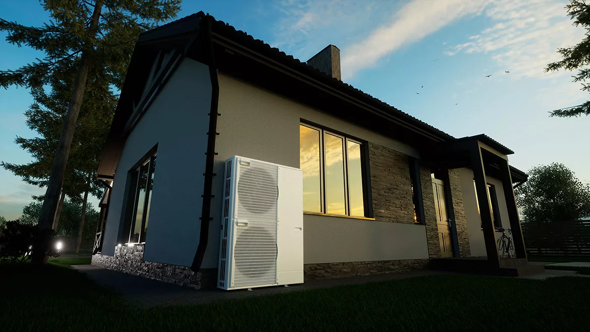
Lead image courtesy of Dmytro Tomson / iStock / Getty Images Plus
Air-to-water heat pumps are becoming increasingly common as primary heat sources in North American hydronic systems. This transition is likely to continue. As it does, some practitioners are learning - sometimes painfully - that heat pumps are not boilers.
When boilers were paired with poorly matched balance-of-system design, it was common for installers to keep turning up the water temperature to compensate for poor heat transfer elsewhere in the system. In some cases, the higher water temperatures eventually “overpowered” the heat transfer bottlenecks, albeit at reduced efficiency, and at exhaust gas temperatures that PVC pipe was never meant to handle.
One example is a system where a boiler supplies a “plate-less staple-up” underfloor heat emitter. The PEX tubing is stapled to the bottom of the subfloor or the sides of the floor joists with a hope and a prayer that the heat released from those plastic tubes would be sufficient to heat the room above. I’ve lost track of how many inquiries we’ve received over the years where this has been done. Those inquiries usually came at the time where everyone involved in the project (wholesaler, contractor, homeowner) were extremely frustrated, and the next step in resolving the problems often involved an attorney.
Another “assembly” that can cause thermal bottlenecking is a monobloc air-to-water heat pump connected to a coil heat exchanger within a tank, as represented by figure 1.
FIGURE 1

Drawing courtesy of John Siegenthaler
The thinking behind this assembly is to create a closed loop circuit between the heat pump and buffer tank that operates with an antifreeze solution. Doing so would reduce the amount of antifreeze needed compared to a design that used antifreeze throughout the system.
Although the concept shown in figure 1 is rational, the numbers related to heat transfer issues usually don’t support it.
To see why, start with the fundamental formula for convective heat transfer, in this case applied to the outer surface of the coil heat exchanger.
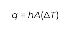
Image courtesy of John Siegenthaler
Where:
q= rate of heat transfer (Btu/hr)
h = convection coefficient on outer surface of coil (Btu/hr/ft2/ºF)
A = outer surface area of coil (ft2)
∆T = temperature difference between the outer coil surface and the bulk fluid into which heat is moving (ºF)
Although this formula is mathematically simple, getting the value of (h) to use in the formula is anything but simple. If you reference a heat transfer textbook or the ASHRAE Handbook of Fundamentals you’ll find that determining a value for the convection coefficient (h) for a horizontal tube delivering heat to a fluid by natural convection on its outer surface requires calculated values for several dimensionless quantities known as the Nusselt number, Grashof number, Prandtl number, and Rayleigh number. Each of these dimensionless numbers require reference to several physical properties of the fluid such as density, viscosity, specific heat, thermal conductivity and thermal expansion coefficient, all of which are temperature dependent. It can all be done (I did it back in college), but it’s a very tedious set of calculations.
That’s where the Internet comes in. Check out https://quickfield.com/natural_convection.htm. It’s a website that grinds through the number crunching for these calculations. Using this site, and assuming that the outer coil surface of the coil heat exchanger was maintained at 120 ºF to deliver heat into the tank water at 110 ºF, the convection coefficient calculates to 90.2 Btu/hr/ft2/ºF.
Looking up some of the specifications on tanks with internal coils I found one “high output” model with a volume of 60 gallons, and a total coil surface area of 15.1 ft2.
With antifreeze flowing through the inside of the coil so that its outer surface is maintained at 120 ºF, and 110 ºF water in the tank, the heat transfer rate from the outer surface of the coil is estimated as follows:
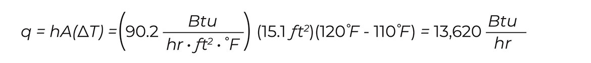
Image courtesy of John Siegenthaler
The far below the average heat output rate for a 4-ton (48,000 Btu/hr) or 5-ton (60,000 Btu/hr) heat pump. To make matters worse, this rate of heat dissipation is likely overestimated. It’s based on a single horizontal tube with an outside diameter of 1.25” immersed in water, and having a total surface area of 15.1 square feet. The helical coil in a typical indirect water heater would have “stacked” horizontal tubes. Due to buoyancy effects, the tubing higher up on the coil is going to “feel” water that’s warmer compared to the tubing at the bottom of the coil. This decreases the temperature difference driving heat dissipation and lowers the rate of heat transfer.
Question: What happens when an air-to-water heat pump delivers heat to the antifreeze solution at say 48,000 Btu/hr, but the coil heat exchanger can only extract heat from that fluid at 13,620 Btu/hr?
Answer: Because heat input rate is much higher than heat dissipation rate, the antifreeze solution circulating between the heat pump and coil quickly heats up. If the heat pump has a single speed compressor the heat pump likely turns itself off based on some preset upper temperature limit. This leads to short cycling. If the heat pump has a variable speed compressor, and controls that speed based on leaving water temperature, the compressor will slow down and the rate of heat output will drop. In either case there’s no way that the full output of the heat pump can be delivered to the water surrounding the coil heat exchanger.
A classic symptom of such a situation is a low temperature drop across the coil heat exchanger when the heat pump is operating. For example, assuming the heat pump to tank coil circuit was operating at a flow rate of 11 gpm, with a 30% solution of propylene glycol, the temperature drop across a coil that’s dissipating 13,620 Btu/ hr would be:
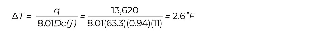
Image courtesy of John Siegenthaler
Where:
∆T = temperature drop (ºF)
q = rate of heat transfer (Btu/hr)
D = fluid density (lb/ft3)
c = fluid specific heat (Btu/lb/ºF)
f = flow rate (gpm)
8.01 = unit conversion factor
What to do: Assuming that the heat pump manufacturer requires the use of antifreeze in their monobloc air-to-water heat pumps - and most do - there are three possible ways to correct this heat transfer bottleneck:
- Find a tank with a much larger internal coil (i.e., 4 times more coil surface area than the “high output” tank referenced in the calculations above). By the way - good luck…
- Use a properly sized flat plate heat exchanger between the heat pump and balance of system.
- Eliminate the need for a heat exchanger by operating the entire system on the antifreeze solution.
The first option is all but impossible, at least for now in North America. Like most components, tanks with internal coils are made to compete against other tanks with internal coils. In North America, most of these tanks are marketed as indirect water heaters supplied by boilers that can operate at relatively high temperatures (180-200 ºF).
Designing and manufacturing such a tank with a much larger internal coil would necessitate a significantly higher selling price. The manufacturer would be “betting” that such a tank would be accepted in the market by those who both understand and need the higher performance, and are willing to pay substantially more for it. From a business standpoint, most manufacturers would be hesitant to take that risk.
The second option is definitely workable. In a flat plate heat exchanger, both fluids release and accept heat through forced convention. That produces much higher convection coefficients relative to the natural convection occurring on the outer surface of an immersed coil heat exchanger. Manufacturers of flat plate heat exchangers provide software that designers can use to size the heat exchanger for the maximum rate of heat transfer required. When used between a heat pump and the remainder of the system, I suggest that the heat exchanger be sized for a maximum approach temperature difference of 5 ºF. Even lower approach temperature differences are preferred when the economics are justifiable.
When boilers were paired with poorly matched balance-of-system design, it was common for installers to keep turning up the water temperature to compensate for poor heat transfer elsewhere in the system.
Keep in mind that using a flat plate heat exchanger in this application requires two circulators to run whenever the heat pump is running. The closed loop between the heat pump and heat exchanger also needs an expansion tank, pressure relief valve, fill / purge valves, pressure gauge, and (ideally) an air separator.
Designing the system to use antifreeze throughout is the simplest approach. it’s also going to allow the heat pump to attain a higher seasonal COP since it doesn’t have to operate at least 5 ºF above the temperature of the water on the secondary side of the heat exchanger.
The take away: There can be a huge difference in thermal performance between heat exchangers that operate with natural convection versus forced convection, the latter allowing much higher rates of heat transfer per unit of heat exchanger area.
Tanks with internal coil heat exchangers certainly have their place in hydronic system design, but it’s essential to evaluate the heat transfer ability of the coil in the context of the application. Moving heat from 120 ºF antifreeze in the coil to 110 ºF water in the tank is a lot different than moving heat from 190 ºF boiler water to domestic water at 110 ºF.
Until such time that buffer tanks equipped with a very large internal heat exchanger become available I suggest using option 2 or 3 above. Don’t bottleneck the BTUs between the heat pump and the intended load.
Looking for a reprint of this article?
From high-res PDFs to custom plaques, order your copy today!


