The Glitch & The Fix: February 2025
A heat pump heat migration problem
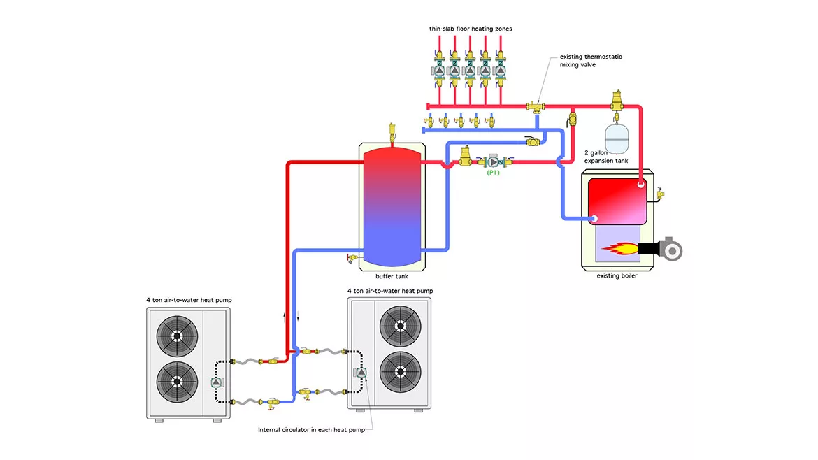
Image courtesy of John Siegenthaler
The Glitch
A heating contractor is asked to install two identical air-to-water heat pumps to take over as the primary hydronic heat source for a large home. Each heat pump has its own internal circulator. The existing boiler will be retained as the supplemental and backup heat source. A standard multi-boiler staging controller will be used to operate the heat pumps as rotating stages 1 and 2, and the boiler as “fixed” stage 3. These heat sources will supply several zones of low-temperature thin-slab radiant floor heating.
The existing system uses a 1.5” pipe size thermostatic mixing valve to reduce the water temperature from the boiler to the floor circuits.
After the heat pumps are added, there’s noticeable heat migration into zones that are supposed to be off. The galvanized vent connector from the boiler to the chimney also has to be periodically replaced due to corrosion.
The system — as installed — is shown in Figure 1. The piping layout was meant to salvage as much of the original installation as possible. Can you identify some problems with this design and suggest modifications that would correct them?
FIGURE 1

Image courtesy of John Siegenthaler
The Gitches
- Although each heat pump has its own circulator, each heat pump doesn’t have its own check valve. When one heat pump circulator is on and the other is off, some of the flow from the active heat pump circulator will pass in reverse through the inactive heat pump. This reduces flow to the buffer tank and increases the entering water temperature to the active heat pump.
- Another issue is created by circulator (P1) in Figure 1. When operating this circulator is partially in series with the zone circulators. The differential pressure it creates is sufficient to push heated water through the check valves in the inactive zone circulators, which is the underlying cause of the heat migration.
- The corrosion of the vent connector pipe is due to a lack of anti-condensation protection for the oil-fired boiler. As built, low-temperature water returning from the radiant floor circuits goes directly into the boiler. That water holds the temperature on the combustion side of the boiler’s heat exchanger below the dewpoint of the exhaust gases causing them to condense into an acidic liquid. From the standpoint of chemistry, a galvanized steel vent pipe is no match for that liquid. Holes through the pipe can form in a few months.
- Adding a buffer tank to the system significantly increases the system’s volume. The existing expansion tank should be checked to see if it is large enough to accommodate the total expansion volume of the modified system. A 2-gallon tank is not large enough. Converting the system from water to a mixture of propylene glycol further exacerbates the issue since antifreeze solutions have a higher volumetric expansion rate relative to water. It’s likely that this system should have a nominal 7-gallon (or larger) expansion tank.
- The thermostatic mixing valve may have worked when the boiler was the sole heat source, but it’s not needed after the heat pumps take over as the primary heat source. There is no point in operating the heat pumps at leaving water temperatures higher than currently required by the space heating load, and then mixing that temperature down. The temperature of the buffer tank should be maintained based on outdoor reset control and the thermostatic mixing valve eliminated.
- Since there are valves for isolating either heat pump during service, there should also be a pressure relief valve between those valves and the heat pump. It needs to be there to protect against over-pressure in the unlikely (but possible) event that the heat pump was turned on while isolated from the remainder of the system.
The Fixes
Figure 2 shows one way to modify the system to correct all of the above issues with minimal disruption of existing piping and components.
FIGURE 2
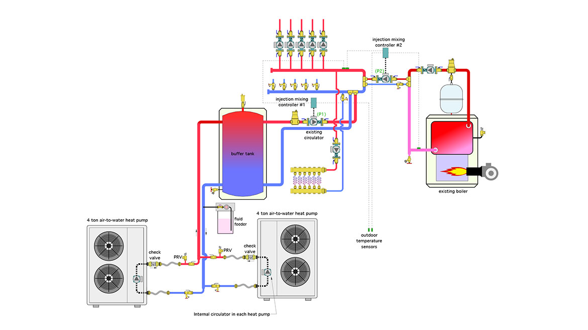
Image courtesy of John Siegenthaler
Check valves have been added to the outlet connection on each heat pump to prevent flow reversal when only one heat pump is operating.
Existing circulator (P1) is now regulated by a variable speed injection mixing controller that monitors the supply temperature to the zone circuits and “injects” heated water from the buffer tank as necessary to maintain a target supply water temperature to the zones. This eliminates the need for the thermostatic mixing valve.
Although it would be possible to just operate circulator (P1) at a fixed speed doing so could lead to “over pumping” when the total flow rate of all active zones is less than the flow through (P1). The result would be heated water returning to the lower portion of the buffer tank and disrupting beneficial temperature stratification within the tank. If the total flow rate of all active zones was higher than the flow through (P1) (e.g., “under pumping”) some of the flow returning from the zones would pass through the closely spaced tees, mix with the heated water from the buffer tank and reduce the supply temperature to the active zone. Both of these scenarios are prevented by supply temperature feedback to the injection mixing controller.
A pair of closely spaced tees creates the necessary hydraulic separation between circulator (P1) and the zone circulators, eliminating the previous heat migration into inactive zone circuits.
The boiler is also interfaced to the zone distribution system using a second injection mixing circulator. That controller monitors the supply water temperature whenever the boiler is operating (which should be infrequently now that two heat pumps are in the system as primary heat sources). The speed of the circulator is adjusted to maintain a target supply water temperatures based on outdoor reset. The injection controller also monitors the boiler inlet temperature and limits heat transfer away from the boiler as necessary to prevent sustained flue gas condensation. The injection piping interfaces to the zone distribution system through another set of closely spaced tees, which provide hydraulic separation between the injection circulator and the zone circulators.
Additional thoughts
Because the new heat pumps have variable speed compressors, they have a nominal 3:1 turndown ratio. Since there are two identical heat pumps the turndown ratio of the heat pump “plant” is 6:1. Given this wide range of capacity control and the relatively high thermal mass of the floor heating system, a hydraulic separator could have been used instead of the buffer tank. This would definitely reduce cost, reduce space requirements in the mechanical room, and displace the need for air and dirt separators elsewhere in the system.
In this scenario the heat pumps would need to have 0-10 VDC input for compressor speed control. The system would be operated by a controller that could stage and modulate the output of each heat pump. A 3-stage controller with a 0-10VDC output to each heat pump, combined with a third on/off output for the boiler would work. Such controllers are currently available.
A thermostatic anti-condensation valve would be used to protect the boiler.
A schematic for this scenario is shown in Figure 3.
FIGURE 3
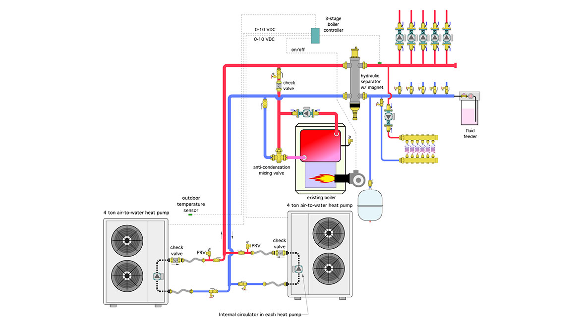
Image courtesy of John Siegenthaler
Looking for a reprint of this article?
From high-res PDFs to custom plaques, order your copy today!


