John Siegenthaler: Opportunities to reduce head loss
One size larger

Nuthawut Somsuk/iStock/Getty Images Plusvia Getty Images.
When designing hydronic circuits, most engineers focus on what’s necessary for that circuit to absorb thermal energy at a heat source, carry it along like a conveyor belt and drop it off at one or more heat emitters.
But thermal energy isn’t the only energy being processed in hydronic systems. Electrical energy is being converted into mechanical energy. In the hydronics industry, the latter is called “head.” Circulators convert electrical energy into head energy.
The efficiency of that conversion can vary from single digits to upwards of 60%. Small, wet rotor circulators, with traditional permanent split capacitor (PSC) motors, operating near either end of their pump curve have very low electrical to head energy conversion efficiency. Larger circulators with more efficient motors, and applied so that they operate near the middle of their pump curve, represent the higher-end of the efficiency range.
The head energy imparted to the fluid by a circulator is eventually dissipated into heat due to friction between fluid molecules, as well as friction between the fluid and surfaces it flows across.
Every hydronic professional understands that there’s a cost associated with operating a circulator. Every kilowatt-hour of electrical energy “fed” to the circulator comes at a price.
Reducing head loss in hydronic systems reduces the kilowatt-hours of electrical energy required to operate them. But do we really think about this enough as we design?
Head to dollars
Consider a closed hydronic circuit constructed of type M copper tubing and having an equivalent length of 200 feet. Assume this circuit needs to convey a flow rate of 6 gpm along a round trip between a mechanical room and the coil of an air handler. What tube size would you normally select for this circuit?
The usual sizing criteria for copper tubing in smaller hydronic systems is to keep the flow velocity no higher than 4 feet per second. That flow velocity corresponds to a flow rate of 6.4 gpm in 3/4-inch type M copper tubing, so, 3/4-inch is likely the common size selected to handle this flow requirement.
My guess is that many of you reading this didn’t have to consult a chart in order to select a 3/4-inch tube for this flow rate. You just knew from previous experience that a 1/2-inch tube was too small and a 1-inch tube was “overkill” for 6 gpm, so you picked the size in between.
Let work in a few simple calculation to see if that was a good choice.
Assuming the 200 foot x 3/4-inch copper tube circuit was carrying water at an average temperature of 120° F it would have the circuit head loss curve shown in Figure 1.
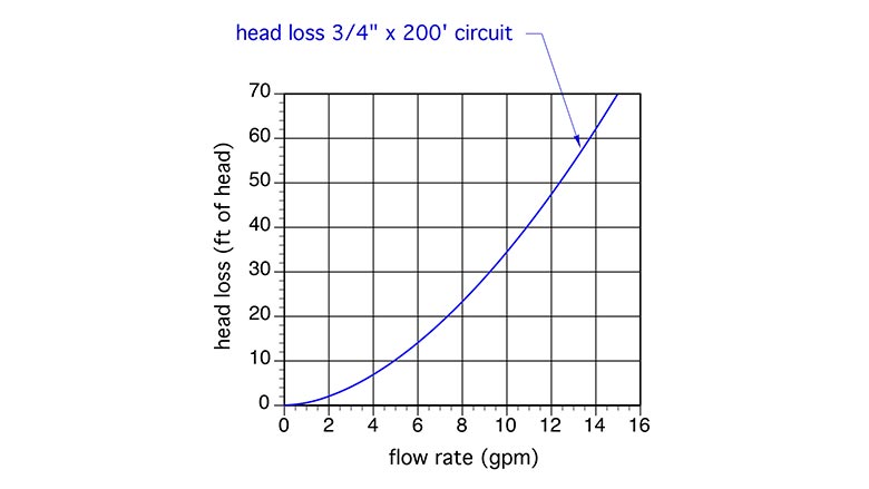 Figure 1
Figure 2 shows the same head loss curve along with the pump curve of a typical small wet rotor “zone” circulator. The point where these two curve cross is the operating point. It’s where the head energy supplied to the water by the circulator exactly matches the head energy dissipated from the water by friction. If you draw a line straight down from the operating point, you can find the flow rate the system will operate at. In this case, it's about 5.9 gpm. Since this flow rate is very close to the target flow rate of 6 gpm, this circulator would be an acceptable selection.
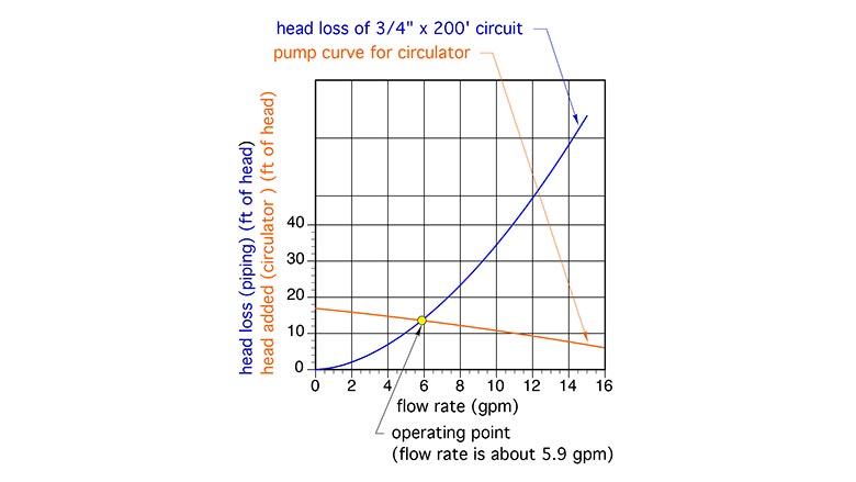 Figure 2
Figure 3 shows the same curves as Figure 2, but adds another curve, shown in green, representing the “wire-to-water efficiency” of a small circulator with a PSC motor. This is the portion of the electrical energy input to the circulator that actually gets converted to head energy.
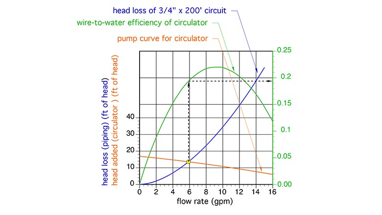 Figure 3
At the operating point of 5.9 gpm, the circulator has a wire-to-water efficiency of 19.5%. That value is not very impressive, but it also not far below the peak wire-to-water efficiency of this circulator, which is about 22%.
Input > output
The owner of a hydronic system doesn’t pay directly for head energy. They pay for the electrical energy needed to operate the circulator that imparts head energy to the water. You can estimate that cost by considering the power input to the circulator, and the total on-time of the circulator.
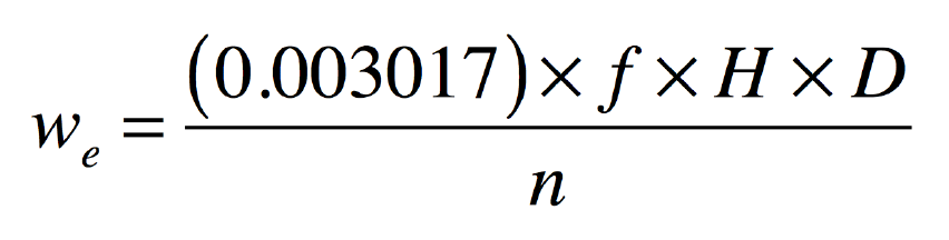
The electrical power input to a circulator can be estimated using Formula 1:
Where:
we = electrical power required by circulator (watts);
f = flow rate in circuit (gpm);
H = head loss of circuit while operating at flow rate (f) (feet of head);
D = density of fluid circulating in system (lb/ft3); and
n = wire-to-water efficiency of circulator operating at flow (f) and head (H) (decimal %).
For the operating point shown in Figure 3, the estimated electrical input to the circulator would be estimated at:
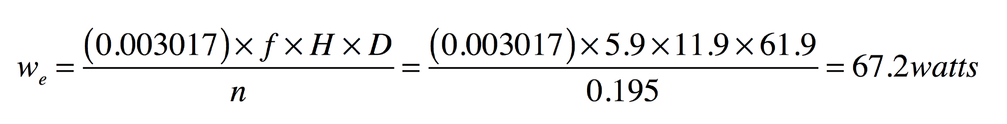
The annual operating cost of any device the requires a known power input, and operates for a known number of hours can be easily calculated using Formula 2.
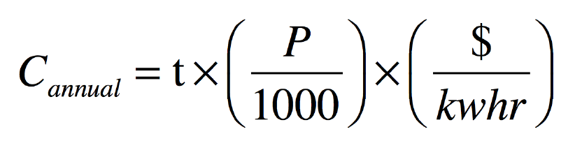
Where:
Cannual = annual operating cost ($/yr);
t = number of hours pump is on per year (hours/yr);
P = input power to circulator (watts); and
$/kwhr = cost of electricity (dollar/kilowatt-hour).
If the circulator represented in Figure 3 operated for 3,000 hours per year, in a location where electricity costs $0.15/kWh, its annual operating cost would be:

Consider upsizing
How would this operating cost change if the circuit was constructed of 1-inch copper tubing rather than 3/4-inch copper tubing? I’m sure most of you know it would go down, but by how much, and is the reduction worth considering?
The head loss curve for a circuit constructed of 1-inch type M copper tubing, and having an equivalent length of 200 feet is shown (in red) in Figure 4.
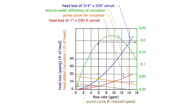 Figure 4
If the same circulator, operating at the same speed setting, was used in this circuit, the flow rate would increase to about 10.2 gpm (as shown by the yellow square at the new operating point in Figure 4). But that’s quite a bit more flow than the target value of 6 gpm. This should prompt the designer to consider operating the circulator at a lower speed, or perhaps look for a different circulator that could bring the operating point back down to around 6 gpm.
Assume the circulator’s speed could be reduced so that its new pump curve is the brown curve in Figure 4. The intersection between the circuit head loss curve for the 200 ft x 1-inch Type M copper circuit and the new pump curve occurs at a flow rate of about 6.2 gpm. This is again close enough to the target flow rate to be an acceptable option.
The head loss at the operating point shown by the yellow triangle in Figure 4 is now about 4.5 feet. Assuming the circulator’s wire-to-water efficiency remains essentially the same at the reduced speed, the electrical input to the circulator is now estimated as:
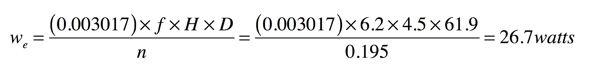
The annual operating cost of the circulator under the same conditions as previously assumed (3000 hours per year and $0.15/kWh) would now be $12.02.
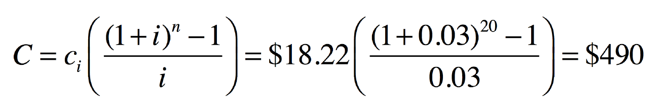
The 1-inch tubing combined with operating the circulator at lower speed produces about the same flow rate using 60% less electrical input. Although that reduction should get anyone’s attention, you may still think that the difference in operating cost of $18.22 per year is trivial. However, little differences add up over time. If we assumed that the cost of electrical energy increased at 3% per year, and totaled this difference in operating cost over a 20 year period, the total operating cost savings for using 1-inch rather than 3/4-inch tubing would be:
Obviously it costs more to construct the circuit using 1-inch rather than 3/4-inch tubing, and this added cost would have to be deducted from the life cycle saving associated with lower operating cost. Still, it’s likely that the “net” savings in operating cost would exceed the added installation cost within 20 years, and perhaps much sooner in areas where electricity is more expensive.
Be vigilant
If your goal is to maximize the technical advantages of hydronic versus air-based heat delivery, you should always be looking for ways to reduce the pumping power requirements of your systems.
Consider the head loss characteristics of the heat sources, heat emitters, dirt separators, mixing valves, heat exchangers, and other components you select. The lower they are, the lower the potential operating cost of the system. Don’t “settle” on high head loss components if there are competitive options available with lower head loss.
The automotive and aerospace industries has been working for decades to reduce the drag of vehicles they produce. Lower drag results in high fuel efficiency, and both of these industries have achieve major advances in fuel efficiency compared to 40 years ago.
The hydronic equivalent of this is would be designing components and circuits with lower head loss. If you’re a manufacturer, don’t take a dismissive attitude that installers will just have to use larger circulators to accommodate the head loss requirements of your hardware, and thus it’s not “your problem.”
Some mod/con boilers with compact heat exchangers require a dedicated circulator that can draw over 200 watts. The sole function of that circulator is to move flow through the boiler at an acceptable rate. Separate circulators are required for the distribution system.
Several decades ago there was no need for dedicated boiler circulators in single boiler systems. The head loss of a cast iron sectional boiler was low enough that the distribution circulators could easily move flow through the entire system.
That’s still the case for cast-iron boilers, as well as some contemporary hydronic heat sources where low head loss was an integral part of the design objectives. In other products it appears that hydraulic efficiency has been willingly sacrificed for gains in thermal efficiency, reduced materials, or smaller size.
Such tradeoffs aren’t limited to boilers. Some water-to-refrigerant heat exchangers used in water-to-water or air-to-water heat pumps also have a ravenous appetite for head energy, (for example, an air-to-water heat pump that requires 31 feet of head at 10 gpm flow rate). Some geothermal earth loop circuits with minimal pipe sizes, and circulators with PSC motors, require upwards of 1,000 watts of circulator input power. This power requirement is often ignored. Instead, attention gets focused on impressively high coefficient of performance (COP) and energy efficiency ratio (EER). In the end, the owner of that heat pump system doesn’t pay for COP or EER. They pay for kilowatt-hours, whether they go to the compressor, the earth loop circulator(s), or other electrically operated hardware in the system.
To maximize the potential benefits of hydronic systems engineers should be vigilant in looking for opportunity to reduce head loss.
Looking for a reprint of this article?
From high-res PDFs to custom plaques, order your copy today!


