John Siegenthaler: Why geothermal earth loops need expansion tanks
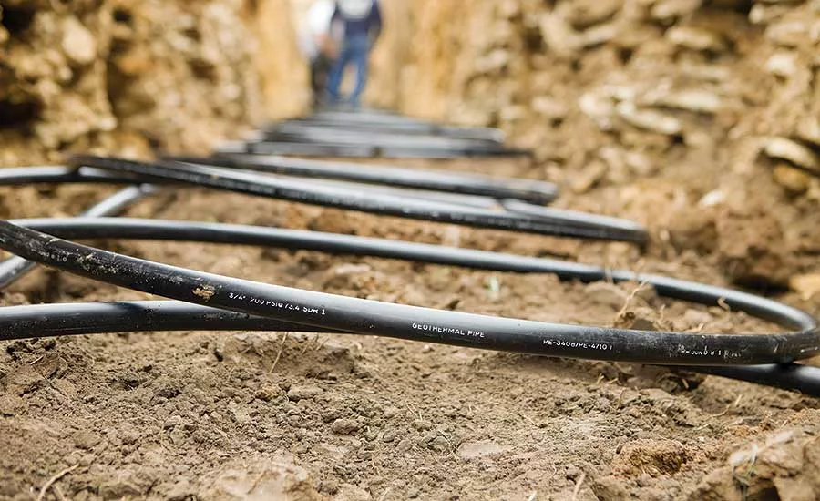
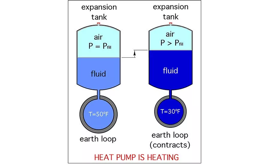
Figure 1
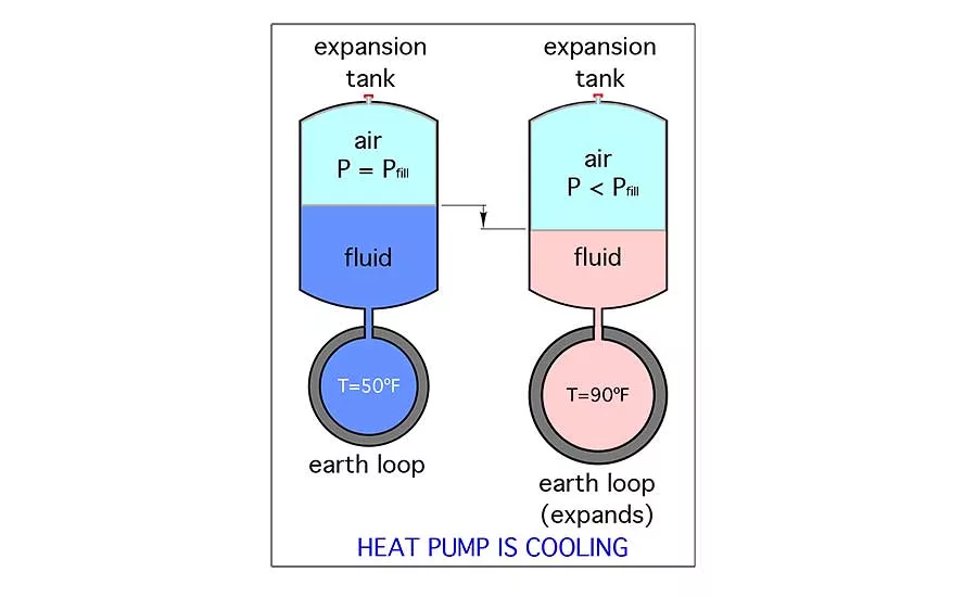
Figure 2
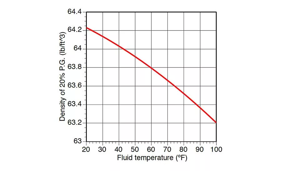
Figure 4
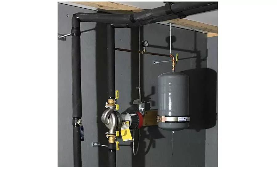
Figure 5
There are sorted opinions about using expansion tanks within closed geothermal earth loops.
Some say the tank is not necessary because the HDPE tubing from which the loops are built will itself expand and contract to absorb the expansion and contraction of the earth-loop fluid. Thousands of earth loops have been installed without expansion tanks, primarily in North America. Some have operated acceptably, while others have experienced pressure variations that have caused problems.
In Europe, things are different. Most geothermal heat pump installations include an expansion tank as a standard part of the earth loop. The reasoning is sound: An expansion tank reduces pressure fluctuations and averts some of the problems associated with “tankless loops.”
I agree with that reasoning, and recommend that an expansion tank should be used in every closed earth-loop circuit. The following facts support this recommendation.
- One characteristic of earth loops is that the antifreeze fluid within them expands and contracts at a different rate than the volumetric expansion and contraction of HDPE piping. As the earth-loop fluid and piping cool, the internal volume of the HDPE piping decreases faster than the volumetric contraction of the fluid. This causes a pronounced increase in loop pressure in systems not equipped with expansion tanks. This pressure rise in-creases the potential for fluid leaks at piping connections.
- When the heat pump is operating in cooling mode, the temperature of the earth loop fluid and piping increase. The internal volume of the HDPE piping increases faster than the volumetric expansion of the fluid. This causes a drop in earth-loop pressure. In systems without an expansion tank, the fluid pressure at the inlet of the earth-loop circulator can drop low enough to cause cavitation. A cavitating circulator will not produce proper flow rates, creates unacceptable noise levels and will eventually fail due to erosion of the impeller or volute. Installing an expansion tank in the earth loop is one way to avoid such problems.
Figure 1 shows fluid being pushed into the expansion tank from the contracting earth loop when the heat pump is operating in heating mode (e.g., earth-loop temperature is decreasing).
Figure 2 illustrates fluid flowing out of the expansion tank into an expanding earth loop when the heat pump is operating in the cooling mode (e.g., earth-loop temperature is increasing). The minimum and maximum earth-loop temperatures indicated are typical.
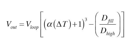
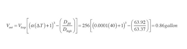
Formula 1 can be used to determine the volume of fluid drawn out of the expansion tank as the earth loop temperature increases during cooling mode operation:
Formula 1:
Where:
Vout = Volume of fluid flowing out of expansion tank (gallons).
Vloop = Total volume of earth loop when filled and purged (gallons).
α = Coefficient of linear expansion of earth loop piping (in/in/ºF).
∆T = Absolute value (e.g., always a positive number) of temperature change of loop (ºF).
Dfill = Density of fluid when loop is filled and purged (lb/ft3).
Dhigh = Density of fluid when loop is at maximum temperature (lb/ft3).
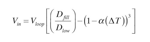
Formula 2 can be used to determine the volume of fluid added to the expansion tank when the earth-loop temperature drops during heating mode operation.
Formula 2:
Where:
Vin = Volume of fluid flowing into of expansion tank (gallons).
Vloop = Total volume of earth loop when filled and purged (gallons).
α = Coefficient of linear expansion of earth loop piping (in/in/ºF).
∆T = Absolute value (e.g., always a positive number) of temperature change of loop (ºF).
Dfill = Density of fluid when loop is filled and purged (lb/ft3).
Dlow = Density of fluid when loop is at minimum temperature (lb/ft3).
Here’s an example of how to use these formulas. Assume that an earth loop contains 5,000 feet of 1-inch DR-11 DPE tubing, and 200 feet of 1.5-inch DR-11 HDPE pipe. The earth loop is filled with a 20% solution of propylene glycol. The system is filled with this solution when the earth- loop piping and fluid are both at 50º F. Determine the amount of fluid extracted from the expansion tank when the loop temperature increases to 90º F, and the volume of fluid added to the expansion tank when the loop temperature drops to 30º F.
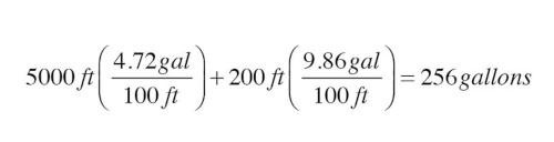
The total volume of the DR-11 HDPE earth-loop piping can found from Figure 3:
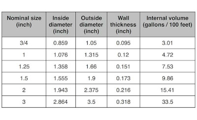
The total fluid volume in the earth loop is:
The density of a specific 20% propylene glycol fluid at the stated temperatures can be referenced in Figure 4.
For 20% propylene glycol at 90º: D = 63.37 lb/ft3;
For 20% propylene glycol at 50º: D = 63.92 lb/ft3; and
For 20% propylene glycol at 30º D = 64.14 lb/ft3.
The coefficient of linear expansion for HDPE tubing is 0.0001 in/in/ºF.
The amount of fluid removed from the expansion tank when the loop is raised from 50º to 90º would be:
The amount of fluid added to the expansion tank when the loop is lowered from 50º to 30º would be:

These values are the net volume changes resulting from the combination of expansion and contraction of the fluid, as well as that of the earth-loop tubing.
Sizing the tank
Once the net change in volumes are determined, an expansion tank can be selected that accommodates these volumes within an acceptable change in pressure. Here’s an example of the calculation.
Determine the minimum expansion tank volume required to accommodate the previously determined fluid extraction of 0.86 gallons, while allowing the initial air-side pressure of 20 psi in the expansion tank to drop to 10 psi. Assume that the expansion tank is initially half-filled with fluid as the loop begins heating up.
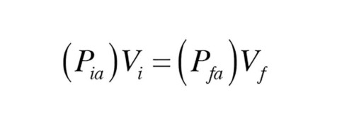
The solution starts by setting up Boyle’s Law for the air volume in the expansion tank.
Formula 3:
Where:
Pia = Initial absolute air pressure in tank (psi).
Vi = Initial volume of air in tank (gallons).
Pfa = Final absolute air pressure in tank (psi).
Vf = Final volume of air in tank (gallons).
Boyle’s law is based on absolute pressure, not gauge pressure. Absolute pressure is determined by adding 14.7 psi to gauge pressure (in psi). Using this relationship, along with the stated conditions, the Boyle’s law formula can be expressed as:
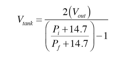
Formula 4:
Where:
Vtank = Required volume of expansion tank (gallons).
Vout = Volume of fluid leaving tank as loop heats to max operating temperature (from equation 14.15) (gallons).
Pi = Initial airside pressure in tank (when loop is charged) (psig).
Pf = Final airside pressure in tank (when loop is at max. temperature) (psig).
Solving Formula 4 for the required (minimum) expansion tank volume yields:
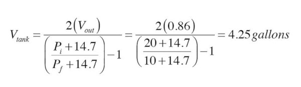
An expansion tank of 4.25 gallons total shell volume initially at 20 psi airside pressure, and half-filled with fluid, will allow the system loop pressure to drop from 20 to 10 psi. This is a reasonable change in pressure that should not adversely affect the operation of a properly installed circulator (e.g., circulator positioned so that it pumps away from the expansion tank connection point). Keep in mind that Formula 4 yields the minimum expan-sion tank shell volume that can meet the assumed conditions. Selecting an expansion tank slightly larger than the calculated 4.25 gallons will further reduce the pressure change in the earth loop.
When setting up this tank, the airside pressure should be adjusted to 10 psig. When the loop is charged to 20 psi, the air volume in the tank will be compressed to half its original volume and thus be at 20 psi. The tank will be half-filled with fluid under this condition. The extra fluid volume in the expansion tank is desirable in systems with air separators. It provides some “makeup” fluid that eventually fills the void left by air being separated and discharged from the earth-loop circuit.
In systems where the earth loop is warmed during the cooling season and cooled during the heating season, the net volume change of the expansion tank should be evaluated in both modes. The expansion tank can then be sized based on the more constraining condition. Typically, this will be the acceptable drop in loop pressure when the heat pump is operating in cooling mode.
Designers can use the formulas presented to experiment with different pressure variations, fluid properties and loop volumes to see the effect on expansion tank sizing.
Mounting the tank
Figure 5 shows interior portions of an earth loop that supplies a nominal 4-ton geothermal water-to-water heat pump.
The 6-gallon expansion tank is mounted vertically with the airside down. This prevents air from being trapped on the fluid side of the tank. The upper portion of the tank and connected 1/2-inch copper tubing is supported by two split ring connectors fastened to 3/8-inch threaded rods. While these rods support the weight of the tank and the fluid it contains, and stabilize the upper piping connection, they do not prevent the tank from being damaged if someone should accidentally bump into it. The HydroClaw bracket, which is screwed to solid framing, stabilizes the lower portion of the tank.
A 1/2-inch ball valve is installed just above the tank. It allows the tank to be isolated from the earth loop, removed and replaced, if ever necessary. There’s also a pressure gauge on the piping between the tank and earth loop. The piping from the tank connects near the inlet of the earth-loop circulator. This ensures that the pressure differential created by the circulator is added to (rather than subtracted from) the static pressure in the loop.
An earth loop is a closed hydronic system. It deserves a properly sized expansion tank as would any other closed hydronic system.
Use the formulas and data presented in this article to size up that tank.
Looking for a reprint of this article?
From high-res PDFs to custom plaques, order your copy today!


