The Glitch & The Fix
Dual boiler layout shortcomings
All diagrams courtesy of John Siegenthaler
The Glitch:
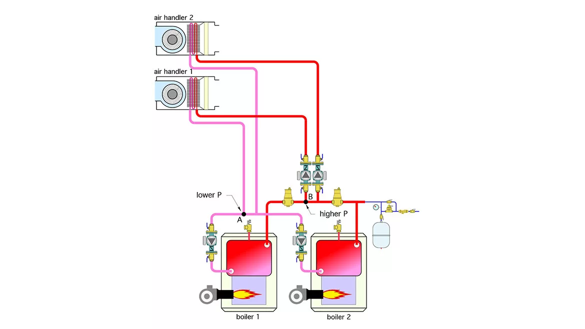
An installer is asked to pipe up two larger commercial air handlers supplied by a dual boiler sub-system. The building owner wants to make it possible to supply either air handler from either boiler. The layout the installer proposed is shown in Figure 1. Can you spot some shortcomings of this layout and suggest a better way to accomplish the same objectives?
FIGURE 1

What’s wrong?
Consider a situation in which boiler 1 is firing to send heat to air handler 1. The circulator on boiler 1 is going to create a pressure differential between points A and B. Point A will be the lower pressure and point B will be at a higher pressure. If this pressure differential is more than about 0.5 psi, it will force flow through the spring check valve in the circulator for air handler 2. This is not desirable. A similar argument holds when boiler 2 is supplying air handler 2, while air handler 1 is supposed to be off.
If you look carefully, you will also see that the coils in the air handlers are not piped for counterflow heat exchange. Since the air passing through the coil is increasing temperature from right to left, the water flowing through the coil should be going in the opposite direction, left to right. This counterflow concept increases the log mean temperature difference between the air and water and thus increases the rate of heat transfer.
The Fix:
Instead of having the circulators interfere with each other, or spending money on two air separators, pipe the system as shown in Figure 2.
FIGURE 2
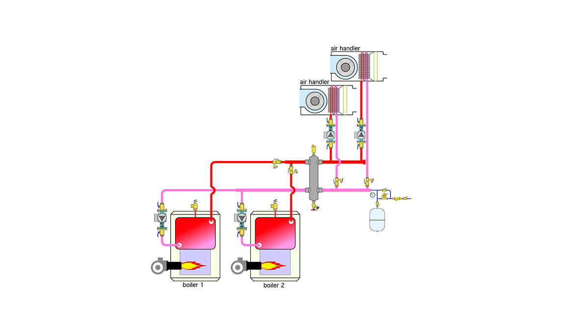
Each boiler connects to generously sized headers that lead to a hydraulic separator. This device also provides central air and dirt separation for the system. Another set of short and generously sized headers connects to the two zone circulators supplying the air handlers. Either air handler can be supplied from either boiler, or both boilers firing simultaneously, if needed. Each boiler can be fully isolated if necessary for service, without affecting the operation of the other boiler. The combination of short generously sized headers and the hydraulic separator prevent interference between the circulators and eliminates “ghost flow” through zones that are supposed to be off.
It would also be possible to use two variable-speed pressure-regulated circulators and 4 zone valves to control which boiler supplies which air handler, as shown in Figure 3.
FIGURE 3
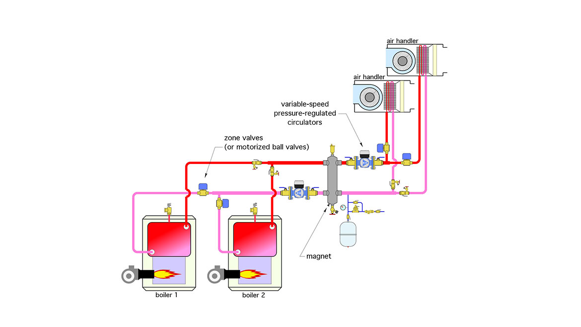
In this case, I would recommend that the hydraulic separator be equipped with a magnet to capture iron oxide particles before they get logged in the rotor cans of ECM circulators.
Also take a look at how the two circulators are located relative to the hydraulic separator and expansion tank. The latter is tapped in close to the lower side connection of the separator. Since there is very little head loss through the separator, each of the circulators is effectively pumping away from the expansion tank — the way they should be.
Keep in mind that the head loss through the two cast iron boilers is very small and that the temperature rise across cast iron boilers can be more than 20° F. This allows a relatively small circulator to provide all the flow that’s necessary on the boiler side of the separator. For example: If each boiler was rated at 200,000 Btu/h, and the temperature rise across the boilers at design load was 30° F, the total flow required would be about 27 gpm (e.g., 13.5 gpm through each boiler). Be sure that the valves used to allow or prevent flow through each boiler are not overly restrictive. They should have a Cv rating approximately equal to the required flow through each boiler.
Looking for a reprint of this article?
From high-res PDFs to custom plaques, order your copy today!


