The Glitch & The Fix
Eliminating the temperature drop effect
Avoiding sequential temperature drops

FIGURE 1
The Glitch:
Primary/secondary systems in which pairs of closely-spaced tees (one for supply and the other for return) are installed along a piping loop and provide hydraulic separation of all the circulators. However, they also create sequential temperature drops as flow in the primary loop gives up heat to each active secondary circuit.
Knowing this, an aspiring hydronics newbie decides that he can eliminate the temperature drop effect by piping a three-zone system as shown in Figure 1. The rational is that putting all three supply-side tees upstream of all three return-side tees will ensure equal supply water temperature to each of the three load circuits. Look this over and see if you’re convinced that this concept will work. If you don’t think it will work, what would you do to change it?
The Fix
In theory, the piping arrangement shown in Figure 1 could work if, and only if, the primary loop flow rate was always greater than or equal to the sum of the three load circuit flow rates. Although this is possible, making sure it happens would needlessly waste electrical power input to the required primary circulator. In short, it’s not a good idea.
Whenever the primary loop flow is less than the sum of the three load circuit flows, there will be flow reversal in some portions of this system. This is illustrated in Figure 2. The primary loop flow rate is 12 gpm, and the three load circuit flows are 6, 10 and 5 gpm.;
FIGURE 2
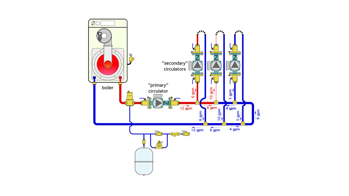
To determine what happens in different segments of the piping just remember that what flows into a tee must flow out of the tee.
In this case, the 10 gpm flow rate into the middle circuit is achieved by combining 6 gpm from the left with 4 gpm from the right. The latter is cool water from the return side of load circuits. The mixing of 6 ppm of “hot” boiler water with 4 gpm of cooler return water will definitely reduce the supply water temperature to the middle load circuit. As if that weren’t bad enough, look what happens in the right side load circuit. The only way to satisfy the balance between incoming and outgoing flows is for 5 gpm of cool water to flow up through that circuit. Sure, there will probably be some heat output from that circuit, but the situation will only get worse as heat continues to be dissipated.
The way to avoid this is to not create the piping shown in Figure 2. Either create a true primary secondary system where pairs of closely spaced tees are used to connect each secondary circuit to the primary loop, or, in my opinion, use the piping layout shown in Figure 3.
FIGURE 3
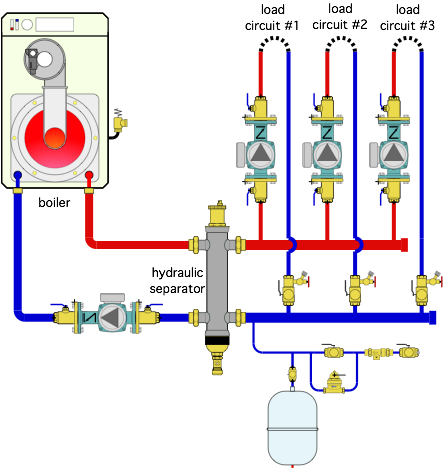
This approach provides the same supply water temperature to each load circuit, hydraulically separates all the circulators, and provides air and dirt separation. The check valves in the circulators prevent reverse flow regardless of which circulators are operating.
Be sure to size the load side headers for no more than 2 feet per second flow velocity when all the load circulators are operating. This “assists” the hydraulic separator in preventing undesired interaction between any operating circulators.
Looking for a reprint of this article?
From high-res PDFs to custom plaques, order your copy today!


.jpg")
