Hydronics Workshop | John Siegenthaler
The ‘ins’ and ‘outs’ of thermal storage
Hydronic systems stand ready to offer performance benefits as electrification movement advances.
Image courtesy of imaginima / iStock / Getty Images Plus
As electrification reshapes the HVAC market, hydronic-based heating and cooling systems stand ready to offer plenty of design and performance benefits. One of them is the potential for thermal storage. After all, water is one of the best materials on earth for storing sensible heat.
Why is storage needed?
The goal of electrification is to shift most of the energy currently supplied by fossil fuels to electricity produced by renewable sources such as large scale solar photovoltaic systems and wind turbine “farms.” We’re moving in that direction, albeit at a slower pace than desired by some politicians and climate activists, and arguably at a faster pace than engineers responsible for stable electric grids are comfortable with. I expect this trend will continue, but I don’t expect that the utopian notion of eliminating all fossil fuels will occur in my lifetime.
The intermittent nature of electrical output from both solar photovoltaic systems and wind turbines sets up the potential for both over-generation and under-generation of energy relative to load. Energy storage, in all viable forms, is the key concept for smoothening the peaks and valleys of energy demand relative to supply.
Huge investments are being made in electric energy storage, typically in the form of lithium-based batteries. They are used at the building level as well as utility level. They work, but they’re expensive and potentially dangerous under certain conditions.
Electrical energy is “high grade” energy. It has the potential to drive processes such as a heat pump compressor that ultimately can provide much more space heating energy per unit of electrical energy input, compared to simply dissipating the electricity into heat. For example, a heat pump operating at a COP (coefficient of performance) of 3.5 would deliver 3.5 times as much heat to a building per kilowatt•hour of electricity used, compared to a simple resistance heating element.Dissipating electricity directly into heat to establish and maintain a 70° F indoor temperature is a waste of thermodynamic potential, which is represented by the term “EXERGY.”
Enter water
Energy storage is not limited to electricity in batteries. Water, combined with heat pumps and time of use electrical rates, can stretch that kilowatt•hour of electrical energy a lot farther, and lower life-cycle costs in the process.
The fundamental concept is to operate a water-to-water, or air-to-water heat pump, whenever possible during “off-peak” hours when utility rates are lower, and store any surplus heat beyond that required by the load in the form of heated water. The stored heat can be used at later times when utility rates are higher.
Many electric utilities offer “time-of-use” electrical rates as an incentive for customers to shift usage to times when the load on the grid is low. The “on-peak” versus “off-peak” times and rates vary considerably from on utility to another. I recently worked on a project where the on-peak rate was $0.44/KWh, and the off-peak rate was “$0.07/KWh. That rate differential presents a very attractive incentive for customers to shift their usage to off-peak times.
For comparison, imagine you could purchase gasoline for $0.64/gallon between 8 p.m. and 7 a.m., versus $4/gallon at all other times. Can you picture the line that would form at any gas station offering such a deal!
Hydronics delivers:
Figure 1 shows one possible piping arrangement that allows one or more electrically-operated heat sources to deliver heat to thermal storage, or directly to the load.
FIGURE 1
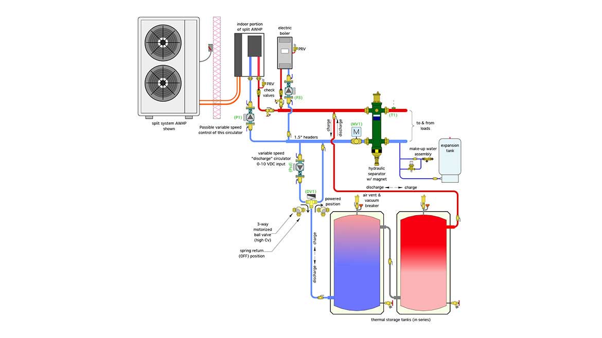
The “split-system” air-to-water heat pump is the primary heat source. The electric boiler provides supplemental heat input when needed and serves as backup to the heat pump if it’s down for service. Both heat sources could be operated simultaneously, if necessary, to maximize energy throughput to storage during favorable off-peak electrical rates.
Each heat source has its own circulator, check valve, PRV and purge valve. The two heat sources are piped in parallel to a common, and generously-sized header.
Thermal storage consists of two well-insulated tanks connected in series. This arrangement, combined with components that allow flow through the coupled tanks in either direction, helps preserve temperature stratification, which is desirable because it increases the potential “usefulness” of the energy relative to a situation where the water in the tanks is fully mixed.
As shown in Figure 1, the coolest water is in the lower portion of the left tank, and the hottest water is in the top portion of the right tank.
When it’s time to charge thermal storage, the heat pump and circulator (P1) are turned on. Likewise, if heat is to be supplied from the electric boiler, it is turned on along with circulator (P2). The motorized valve (MV1) is closed to prevent flow from either heat source from “short-circuiting” through the hydraulic separator. The diverter valve (DV1) is also powered on to provide the “charge” routing for cool water leaving the left side tank. Heated water from either heat source passes into the upper right side of the right side tank, as cooler water is pushed out of the lower connection on the left tank, then back to the heat source(s).
When stored heat is needed by the load, the discharge circulator (Psd) is turned on, the diverter valve switches to the other position (usually by removing power from a spring-return actuator attached to the diverter valve) and the motorized valve (MV1) is opened. Flow passes through the storage subsystem from left to right, sending the hottest water to the inlet of the hydraulic separator.
The hydraulic separator isolates the pressure dynamics of the heat source and storage circulators from that of the distribution circulator(s). It also provides air, dirt and magnetic particle separation.
Injectability
One option enabled by this concept is to control the speed of the circulator (Psd) allowing it to “inject” hot water into the upper left connection of the hydraulic separator. The injected hot water would mix with cooler water returning from the load circuits and passing up through the separator. The injection flow rate from storage would be regulated based on maintaining some desired target supply water temperature at sensor (T1). That temperature could be a setpoint or based on outdoor reset control. The latter would improve the heat pump’s COP because it keeps the supply water temperature as low as possible while still maintaining comfort in the building.
It’s coming
About now you’re probably wondering how such a piping, circulator and valve arrangement can be controlled. The answer depends on several variables, such as when time of use rates are available, the cost differential between on-peak and off-peak rates, the water temperature requirements of the heat emitters (lower is always better) and the priority of maintaining comfort in the building regardless of the status of thermal storage. While I can’t point you to specific off-the-shelf controls at this point, I can assure you that intelligent operation of this system is possible based on relatively inexpensive microcontrollers and custom programming to drive those controllers. I’m confident that such controllers will become available as the push toward electrification continues, and modern hydronics technology provides the solution to more sophisticated energy management.
Looking for a reprint of this article?
From high-res PDFs to custom plaques, order your copy today!


.jpg")