Hydronics Workshop | John Siegenthaler
A simple, repeatable and scalable approach to hydronic distribution
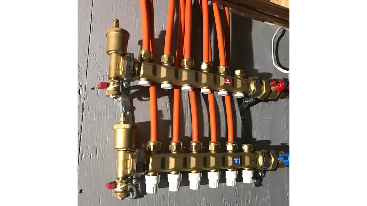
This one works…
One of the best things about hydronic heating is there is virtually no limit to how piping systems can be customized. One of the worst things about hydronic heating is that there is virtually no limit to how piping systems can be customized.
Creative piping design allows experienced hydronic pros to meet the exact needs of custom applications. If you know what you’re doing, it’s possible to combine elements of 2-pipe reverse return, with elements of primary/secondary piping (e.g., closely spaced tees), and more into the same system. You can also combine multiple and different types of heat sources, such as a heat pump and a boiler and even some solar thermal collectors into the same system.
That’s the good news.
The bad news is too many installers don’t understand these design elements well enough to pull off a complex system. The result can be an “undefined piping aberration” that — at best — combines concepts in ways that simply don’t work properly, or at worst — won’t work at all.
The one thing you don’t want to do when designing hydronic systems, especially if you’re new at it, is to attempt to “reinvent the wheel” with each new project.
You would be much better served by studying proven hydronic piping design approaches. Learn the strengths and limitations of each approach, and choose which is appropriate for each upcoming project.
Proven performer
In the context of residential systems, my favorite approach to hydronic distribution is called a homerun system. It allows simple, repeatable and scaleable designs that make good combined use of modern materials and control concepts.
While most of the traditional hydronics system designs were developed around the use of rigid pipe or tubing, homerun systems are based on small diameter flexible tubing such as PEX, PE-RT, or PEX-AL-PEX.
In a homerun system, each heat emitter has a supply and return run of small diameter tubing connecting it to a manifold station. Figure 1 shows a simple example of such a system.
FIGURE 1
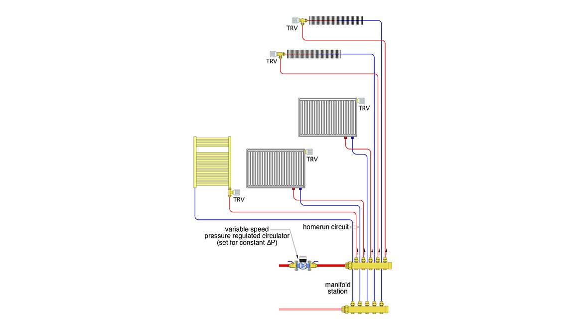
This schematic purposely shows different types of heat emitters. In this case, two homerun circuits go to panel radiators, two others go to fin-tube baseboard and the fifth goes to a towel warmer. It’s also possible to include one or more radiant floor, wall or ceiling circuits, a fancoil or an air handler along with other heat emitters.
Since each homerun circuit is supplied from the same manifold, each receives water at the same temperature. Assuming that heat loss along the individual circuits is small, each heat emitter would receive water at about the same temperature. That alone is a significant improvement over series circuits or diverter tee (a.k.a., Monoflo) distribution system. It makes it easier to size the heat emitters. Just pick the water temperature you want to work with under design load conditions, and size each heat emitter for its associated design load while receiving water at that temperature. I suggest a design load water temperature no higher than 120° F to ensure compatibility with modern heat sources such as mod/con boilers or heat pumps, as well as possible future heat sources that are likely to operate with higher efficiency at lower water temperatures.
Since all the homerun circuits are in parallel, it’s also possible to adjust flow proportions using either the valves on the manifold station, or the balancing adjustment features on many thermostatic radiator valves (a.k.a., TRVs).
Homerun systems are also ideally suited for use with modern high-efficiency variable-speed, pressure-regulated circulators. Set the circulator up for constant differential pressure mode, and at the head or differential pressure (e.g., ∆P) required by the system at design load. Once set, the circulator automatically ramps its speed up or down as the thermostatic radiator valves on the heat emitters open, close or modulate flow. Think of it as “cruise control” for the ∆P across the manifold station.
Not sure how to find that head or ∆P? Just identify which of the homerun circuits has the higher head loss or ∆P. If all the heat emitters are similar, it’s probably the circuit with the longest total circuit length. However, if one of the heat emitters has a high-pressure drop characteristic, that drop should be added to the pressure drop of the associated supply and return piping, at the flow rate the emitter is expected to operate at. The total is a reasonable estimate for the total circuit pressure drop. Convert this pressure drop to head loss and combine it with the total flow rate required when all homerun circuits are operating to get the design load operating point for the circulator.
Ideally, the head loss (or pressure drop) of the manifold and the common piping connecting the manifold to a heat source or buffer tank should be kept as low as practical. This provides the best configuration for a variable-speed circulator operating in constant differential pressure mode.
When TRVs are used on each heat emitter, each homerun circuit can operate as a separate zone. This can lead to “micro-loading,” a condition in which the heating load, at times, can be a small fraction of the heat output rate from the heat source — even a modulating heat source.
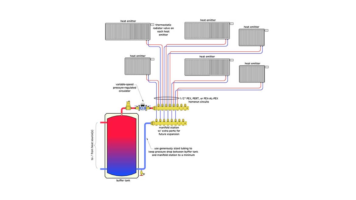
Since all modulating heat sources have minimum outputs, and those outputs are often well above the minimum active heating load, it’s good practice to include a buffer tank between the heat source and the manifold station. The buffer tank reduces the potential for short cycling of the heat source when only one or two small homerun circuits are operating. It also provides good hydraulic separation between the heat source circulator and the variable speed distribution circulator. Figure 2 shows an example of a typical configuration with a buffer tank, variable-speed circulator and homerun distribution system in which each heat emitter is independently regulated by a thermostatic radiator valve.
FIGURE 2
More details:
Take a close look at the manifold station shown in Figure 3.
FIGURE 3
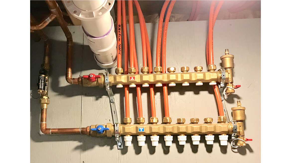
Notice that there are three extra ports on the supply and return manifold. They’re there for future expansion. Suppose that, for example, the owner wants to add a towel warmer or another panel radiator to the system in the future. Just run the flexible tubing back from where it’s located, temporarily close off the valves on the other circuits, and the main valves that connect the manifold station to the rest of the system, and connect the new supply and return tubing to one of those spare ports. Open the valves and let the make-up water system add water. The new emitter is ready to go.
High distribution efficiency
Carefully designed homerun distribution systems using modern ECM-based circulators can be incredibly efficient at transporting heat. Consider, for example, the homerun system shown in Figure 4.
FIGURE 4
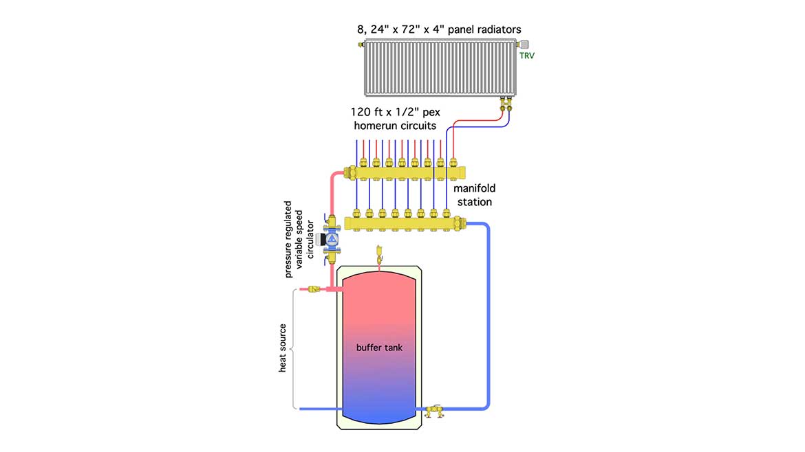
This homerun system serves eight identical panel radiators. Each homerun circuit has 60 feet of 1/2-inch PEX supply tubing along with 60 feet of the same tubing for return. The panel radiators are relatively large because this system will operate at an average water temperature of only 110° F under design load conditions (120° F supply and 100° F return). That’s a good design load water temperature range when a heat pump or mod/con boiler is supplying the heat.
A hydraulic analysis shows that this system can deliver 30,800 Btu/h while operating at a 20° F design load temperature drop, and using only about 10 watts of electric input to the circulator. That works out to a distribution efficiency of 3,080 Btu/h delivered per watt of electrical input to the circulator.
For comparison, a typical residential furnace with a shaded pole blower motor, delivering 80,000 Btu/h while requiring 850 watts input to the blower, has a distribution efficiency of 80,000 / 850 = 94 Btu/h/watt.
This implies that the hydronic system described can deliver heat using less than 3% of the electrical input per unit of heat delivered, compared to that required by that particular furnace. That’s a huge advantage that should be communicated to prospective clients.
While all distribution efficiency comparisons between hydronic and forced air systems may not be quite this extreme, this example shows what’s possible with current technology and good design.
In summary, if you’re tasked with designing a simple residential-scale hydronic heating distribution system and trying to decide on how to pipe it, I strongly recommend consideration of the homerun approach. It’s simple, repeatable, scalable and won’t lead a novice designer into creating an undefined piping aberration.
As we close out 2023, I wish you and your families a blessed and Joyous Christmas.
Looking for a reprint of this article?
From high-res PDFs to custom plaques, order your copy today!


