Hydronics Workshop
John Siegenthaler: Opportunistic pathways
Flow doesn’t always go where you intend.

I recently reviewed a project in which a municipal building was being connected to a district heating system supplied by pellet-fueled boilers. The building’s existing system had two propane-fired mod/con boilers piped into the system as shown in Figure 1.
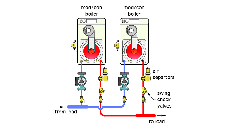
Each boiler has its own circulator that runs only when its associated boiler is called to operate. Each boiler piping assembly contains a check valve to prevent reverse flow when one boiler circulator is on and the other is off. There’s also valving to isolate either boiler, if necessary. What is less typical, but still fine, is that the designer chose to include an air separator on the outlet pipe from each boiler. By all accounts, this subsystem was working fine.
The detour
The district system interfaces to the building’s system through a large plate-and-frame heat exchanger. This is common in district heating systems. It allows heat exchange without mixing the fluid in the district system with that in the building’s distribution system. If necessary, the building’s system can be completely isolated from the district system. A leak or other service issue in one of these systems doesn’t preclude operation of the other system.
The heat exchanger was connected to the existing system using a set of closely spaced tees. A new “bypass” pipe was also installed around the existing boilers. Both modifications are shown in Figure 2.
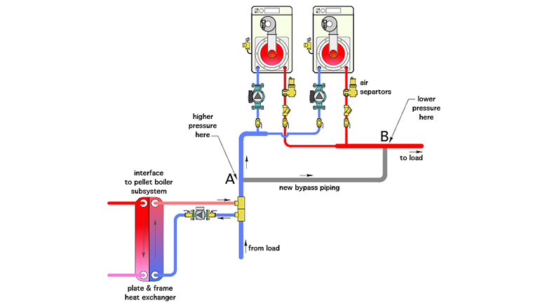
One intent of the piping modifications was to allow heat from the pellet boiler to be injected into the existing distribution system while providing hydraulic separation of the heat exchanger circulator from either of the circulators on the existing boilers, hence the use of closely spaced tees to connect the heat exchanger to the existing piping.
Another intent was to allow flow, which already had heat added to it from the heat exchanger, to go around the existing boilers, since both of the circulators on these boilers would be off. This did occur — to some extent.
Why “to some extent?” The unintentional consequence of the piping assembly shown in Figure 2 is that there is head loss in the bypass piping between points A and B. The dynamic pressure is slightly higher at point A relative to point B due to this head loss. This pressure differential drives a portion of the flow entering point A through the existing boilers, even when their circulators are off. The forward opening resistance of the swing check valves in the boiler piping is very low and cannot prevent this flow migration.
The temperature of the water entering point A is relatively high — about 180° F at design load. The flow migration through the existing boilers has caused high-limit “lockouts” of the existing boilers. When the system is receiving adequate heat from the pellet boiler, this lockout is not necessarily a problem. However, the next time the existing boilers are called to operate, this lockout must be manually cleared from the control system to re-enable boiler firing.
The migration of hot water through the existing boilers while they are off also increases jacket and convective heat loss from the boilers into the mechanical room. While it’s arguable, in this case, that the heat loss is still within the thermal envelope of the building, it’s also arguable that it represents a loss of control over where that heat is intended to go.
Resolving the issue
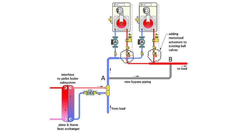
There are several ways this issue could be corrected. One is to modify the existing ball valves on the outlet piping from the boilers so that motorized actuators could be added. Each actuator would open its ball valve prior to allowing the associated boiler to fire. This opening would be verified by the closing of the end switch contacts within the actuator. A spring return mechanism within the actuator would close the valve when the boiler stops firing. This approach is illustrated in Figure 3.
Another option is to remove the pressure drop created by the bypass pipe. This could be done using closely spaced tees or a hydraulic separator. Figure 4 shows how the piping could be rearranged around a new set of closely spaced tees.
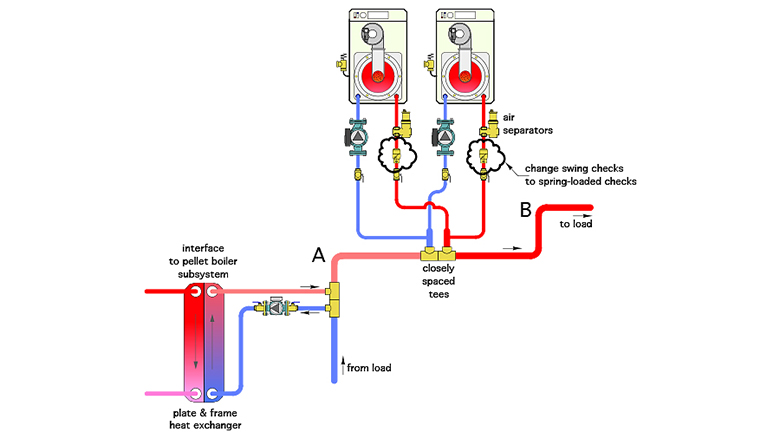
Because there is virtually no pressure drop between the new set of closely spaced tees, there is very little “motivation” for flow to pass through either of the mod/con boilers when their associated circulators are off.
However, the pressure drop between the closely spaced tees is not zero. Thus, to prevent any flow through the mod/con boilers when they’re off, the swing check valves in the original boiler piping should be changed to spring-loaded check valves, with a forward opening pressure of at least 0.5 psi.
This arrangement of the closely spaced tees keeps the heat injection point from the biomass boiler subsystem upstream of the injection point for heat from the existing boilers. This allows the thermal storage tank, which supplies the higher temperature side of the heat exchanger, to drop to the lowest possible temperature before having to fire the pellet boiler for the next heat input cycle. It also allows for heat input from the heat exchanger with simultaneous supplemental heat input from the existing boilers.
The simpler the better
Of these two options, the addition of motorized actuators to the existing ball valves — if possible — would be the simplest, least invasive and likely least expensive modification.
The takeaway is that even relatively short “bypass” pipes have head loss and create associated pressure differentials. Always consider how these pressure differentials — even though small — can induce flow through portions of the system where it’s not desirable. Use the concept of hydraulic separation, which can be implemented through a variety of hardware configurations, to minimize or eliminate extraneous flows and their accompanying heat losses.
Looking for a reprint of this article?
From high-res PDFs to custom plaques, order your copy today!


