John Siegenthaler: Unique circumstances
Multi-zone heating, single zone cooling.
As global energy planning moves away from fossil fuels and toward electricity, an increasing number of hydronic heating systems are being supplied by heat pumps. Some use water-to-water heat pumps supplied by geothermal earth loops. Others use air-to-water heat pumps. Both types can supply warm water for heating, chilled water for cooling and some or all of the domestic water heating load.
To buffer or not to buffer
If the heat pump with a fixed speed compressor supplies a zoned distribution system, it is essential to use a buffer tank in both heating and cooling mode. If the heat pump has a variable speed, (e.g., “inverter”) compressor, a buffer tank may or may not be required. If the latter heat pump can reduce both its heating capacity and cooling capacity to approximately the design load of the smallest zone — or less — a buffer tank is not required. However, this scenario is currently the exception rather than the rule. This is especially true for highly zoned systems or system with more heating zones than cooling zones.
One unique scenario is when there are multiple heating zones — many of which have heat output rates lower than the lowest heating capacity of the variable speed heat pump — being combined with a single zone air handler for cooling. In this scenario a buffer tank needs to be used in heating mode, but not in cooling mode.
This sets up another unique possibility where the buffer tank can buffer both the space heating zones and provide a significant percentage of the domestic water heating load. This type of tank is sometimes called a “reverse” indirect. Several North American manufacturers now offer this type of tank. One possible system configuration using such a tank is shown in Figure 1.
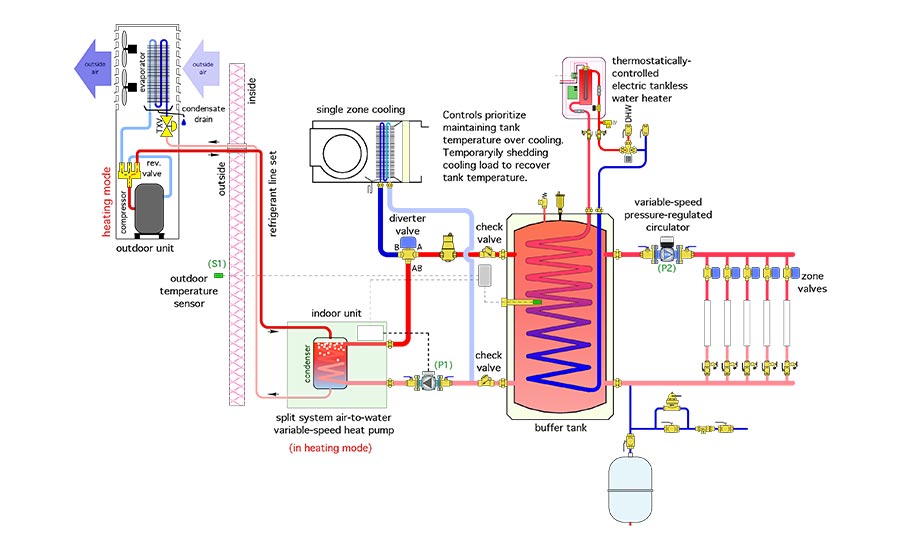
In heating mode, the heat pump maintains the water temperature in the buffer tank. This temperature could be based on a simple setpoint and differential. For example, the heat pump and its associated circulator (P1) could be turned on when the buffer tank temperature sensor drops to 100° F, and off when the sensor temperature reaches 110°.
The heat pump could also be turned on and off based on outdoor reset control. This improves the COP of the heat pump under partial load conditions. Unfortunately, this also increases the amount of supplemental electrical energy needed to bring domestic water to a final (acceptable) delivery temperature.
Which of these control scenarios is “optimal” depends on many factors such as the specific heating and COP performance of the heat pump, the required supply water temperature to the heat emitters, the domestic water heating load and, in the case of air-to-water heat pumps, the climate in which it operates.
Simulations I’ve done based on a low ambient air-to-water heat pump supplying a low-temperature hydronic system (105° supply water at design load), located in upstate New York indicate a slightly higher seasonal COP when the buffer tank temperature is based on outdoor reset control.
Variable speed benefits
In many homes, especially those in cold climates, the design cooling load is significantly lower than the design heating load. This is where a variable speed heat pump is very helpful. It can operate at full output when necessary for design load heating, but “throttle” back on cooling capacity to prevent short cycling. I’ve also found that the outdoor portion of variable speed air-to-water heat pumps are noticeably quieter than similar size heat pumps using single speed “on/off” compressors.
In cooling mode, the flow of chilled water is diverted though the air handler’s coil. It does not pass through the buffer tank. The heat pump’s compressor adjusts its speed to maintain a preset chilled water supply temperature — typically in the range of 45° to 55°.
This allows the buffer tank to be maintained at an elevated temperature to preheat domestic hot water.
When the system is operating in cooling and the temperature of the buffer tank needs to be increased, the system’s controls temporarily interrupts cooling. The heat pump switches to heating mode, and the diverter valve direct flow to the buffer tank. In just a few minutes, the temperature of the buffer tank can be recovered, and the system can switch back to cooling. Keep in mind most heat pumps have an internally-controlled minimum time delay of around 3 minutes between being turned off and then back on. This time allows refrigerant pressure differentials to decrease prior to restart.
When an air-to-water heat pump is used, its heating capacity and COP will be high during summer when cooling is required. This would allow the temperature of the buffer tank to be recovered very quickly. A 5 ton (60,000 Btu/h) heat pump, operating during cooling season conditions, can boost an 80 gallon buffer tank 10° in about 6.6 minutes. It would also be possible to set controls for a slightly higher buffer tank temperature during warm summer conditions to increase the percentage of domestic water preheating, perhaps even to 100%, depending on the required DHW delivery temperature. I suggest a maximum domestic water “preheat” temperature of 120° using the heat pump. If higher DHW temperatures are required use an auxiliary heater.
The thermostatically-controlled tankless electric water heater shown in Figure 1 can provide the supplemental heat needed to bring preheated DHW up to final temperature. A standard tank-type electric water heater could also be used.
Minutia matters
Making this concept work smoothly requires attention to details.
First, be sure that any piping and components that will carry chilled water are insulated and vapor sealed. Don’t get sloppy here. Nature will find the imperfections in your insulation and chastise you in the form of dripping condensate. One product that I really like in these situations is pre-insulated PEX tubing. When the chilled water air handler is located some distance from the mechanical room, this pre-insulated PEX can be routed through the building faster and easier than rigid tubing covered by many custom-cut and glued pieces of elastomeric foam insulation. There will also be far less joints and thus less chances of condensate issues.
Be sure to install the check valves shown to minimize heat migration between chilled water piping and a warm buffer tank.
Finally, use a buffer tank with the largest available internal coil(s). The greater the surface area of the coil, the greater the rate of heat transfer between the tank water and the domestic water in the coil(s).
Efficiency and comfort
This system is a great example of the versatility of modern hydronics technology in adapting a modern renewable energy heat source (e.g., the heat pump) to very specific heating, cooling and domestic water heating loads. It’s also a great fit for new energy-efficient homes, especially those intended to reach net-zero status while maintaining the “gold standard” of comfort that no mini-split or “all air” system will ever deliver. Consider adding it to your portfolio.
Looking for a reprint of this article?
From high-res PDFs to custom plaques, order your copy today!


