John Siegenthaler: A diversionary detail
Another circumstance where hydronic versatility adds value.

The heating output and coefficient of performance (COP) of any hydronic heat pump is very dependent on the water temperature leaving the heat pump’s condenser. The lower this temperature can be and still supply the building’s heating load, the higher the heating capacity and COP of the heat pump supplying that load.
One way to lower the supply water temperature of any hydronic distribution system is to increase the total heat transfer surface area of the heat emitters.
Consider a system in which zoned low temperature radiant panels are selected for space heating, and zoned chilled water air handlers, equipped with condensate drip pans, are selected for cooling.
If the chilled water air handlers were also operated during the heating mode, they would increase the heat emitter surface area of the overall distribution system, and thus lower the water temperature at which the system could supply a given heat output. The hydronic distribution system shown in Figure 1 shows how this can be done.
For simplicity, only one of three radiant panel manifold stations and one of three air handlers are shown in the schematic. The three manifold stations could have different numbers of attached circuits. Likewise, the three air handlers could have different heating and cooling capacities. Whatever the case, all of these devices will operate at the same supply temperature in the heating mode. The three air handlers will operate at the same chilled water supply temperature in cooling mode.
Diversion details
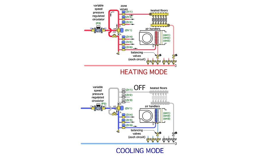
Motorized diverter valves are widely available in North America. They act like a fork in the road. When the actuating motor is off, flow can pass between the ports labelled (AB) and (B). When the actuating motor is on, flow can pass between ports (AB) and (A). Most suppliers offer motor voltage options such as 24 VAC and 120 VAC to accommodate different installation requirements. Some motorized actuators also have end switches that close when the motor is on and the valve ports (AB to A) are fully open. The internal mechanism in the valve might be a “paddle” that moves back and forth between the (A) and (B) ports. It could also be a ball designed for a 3-way valve body. In either case, it’s important to know the Cv of the valve when doing hydraulic calculations. Since the valve is “steering” flow, rather than mixing two flow streams together, higher Cv values are preferred to minimize circuit head loss.
When the system is operating in heating mode, the diverter valve allows flow from its AB port to its B port. This makes warm water from the buffer tank available to all six zone valves.
The zone valves are wired to operate in coordinated pairs. The zone valve that controls flow to a given radiant panel manifold station is paired with the zone valve that controls flow to the air handler in the same zone. The wiring for this will be shown as you read on. During heating mode, the objective is to allow flow to both the radiant panel circuits, and air handler in a given zone, whenever the thermostat in that zone calls for heat.
This system supplies a single water temperature to all emitters. This keeps the system simple in that it eliminates mixing valves. However, designers need to be sure that the radiant panels and air handlers can supply the required heating output at the supply water temperature. I suggest keeping the supply water temperature at design load in the range of 105° F to 120° F. A slight reduction in supply water temperature under partial loads is possible using outdoor reset control. However, I also suggest not allowing the supply water temperature to drop below 100°. This keeps the air temperature supplied by the air handlers within reason.
It’s also important to design the ducting from the air handlers so that the heated air is well mixed into room air above the occupied zone of rooms. This is necessary to prevent drafts. Ceiling or high wall diffusers are also ideal for cooling.
Whenever possible, the air handlers should be located within the building’s thermal envelope. One option is to locate them in accessible compartments above larger closets (in situations where the ceiling height in the closet can be lower than the ceiling in the adjoining rooms. Another possibility is to locate the air handlers in conditioned attics, where the building’s thermal envelope is at the rafters. In all cases, be sure there is sufficient access to service the air handler and its filter. I also recommend a secondary drain pan under each air handler to protect finished ceilings below. If the air handler is mounted over a bedroom closet be sure to provide acoustic separation.
When the system operates in the cooling mode, chilled water can only be delivered to the air handlers, which are equipped with condensate drip pans. Flow to the radiant panel manifold stations is prevented by the 3-way diverter valve as well as closed zone valves on the heating circuits.
Beneficial buffering
When a fixed speed heat pump supplies a zoned distribution system, it is essential to use a buffer tank in both heating and cooling mode. If the heat pump has an inverter (e.g., variable speed) compressor, a buffer tank may or may not be required. If the latter heat pump can reduce both its heating capacity and cooling capacity to approximately the design load of the smallest zone, or less, a buffer tank is not required. However, this scenario is not common, at least with the present ability of inverter compressors. This is especially true for highly zoned systems, or system with more heating zones than cooling zones. In most systems, a buffer tank should be used to prevent the heat pump from short cycling.
Figure 2 shows a split system air-to-water heat pump supplying a buffer tank that’s piped in a “4-pipe” configuration. The heat pump is turned on and off as needed to maintain the water temperature in the buffer tank based on outdoor reset control. This control action is independent of the calls for heating from the zone thermostats.
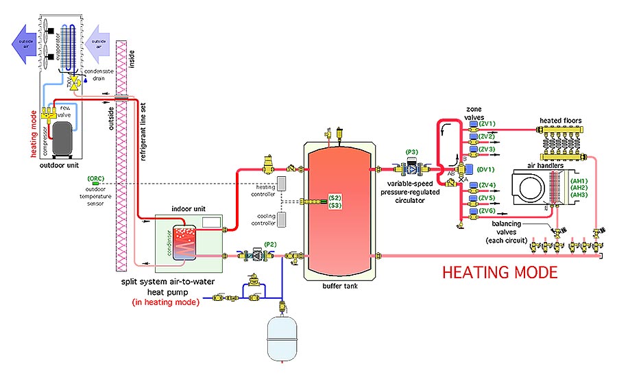
Figure 3 shows the same system in cooling mode.
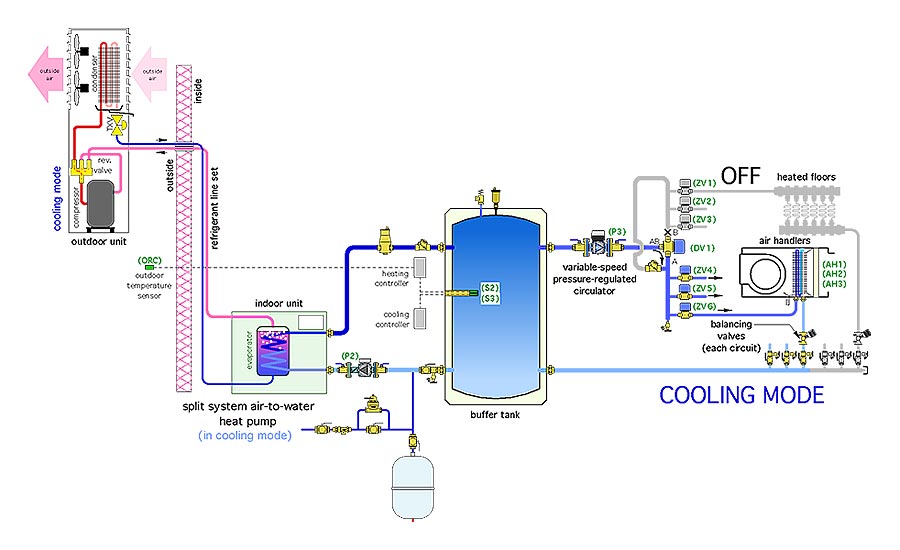
In cooling mode, the heat pump is turned on and off by a temperature setpoint controller, which monitors a sensor in the tank. This control action is also independent of the call for cooling from any of the room thermostats. Thus, chilled water is immediately available when any air handler calls for it. The chilled water is directed from port AB to port A of the diverting valve. A check valve prevents the chilled water migration toward the piping supplying the radiant panels.
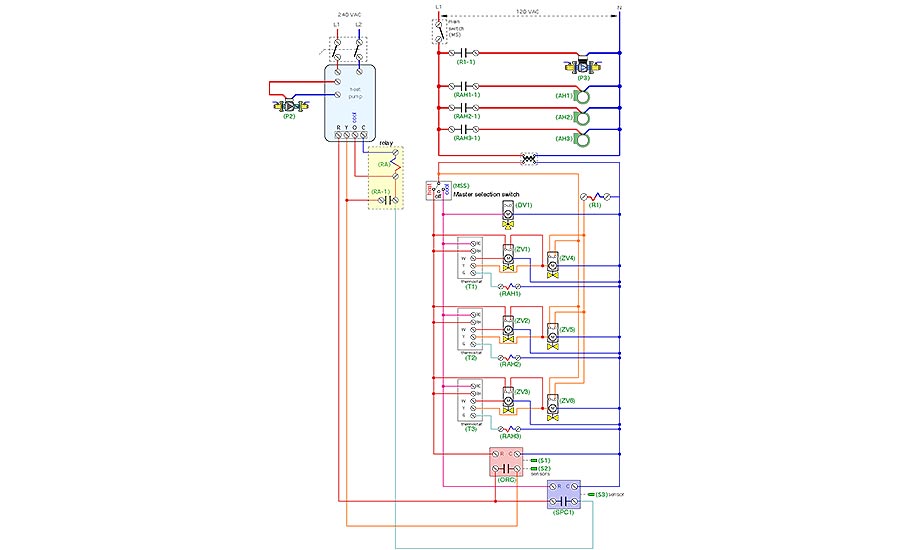
Figure 4 shows one way the system controls can be configured.
The brains
A heat/off/cool master switch determines the system’s operating mode.
In heating mode, 24 VAC from the transformer is passed to the (RH) terminal of each zone thermostat. When that zone needs heat, 24 VAC is passed to the thermostat’s (W) terminal, and on to the actuating motor in a zone valve. When that zone valve fully opens, its end switch passes 24 VAC from the transformer to the actuating motor of the other zone valve for that zone. Thus, both zone valves are open to allow warm water flow to both the radiant panel circuits and the air handler.
In cooling mode, 24 VAC from the transformer is passed to the (RC) terminal of each thermostat. When a zone needs cooling, 24 VAC is passed to the thermostat’s (Y) terminal, and on to the zone valve controlling flow to the zone’s air handler. The other zone valve in the pair is not powered on.
The end switch in the zone valves that controls flow to the air handlers, and thus turns on in both heating and cooling modes, is used to route 24 VAC to a relay that, in turn, operates circulator (P3). That circulator is set for constant differential pressure mode, and automatically adjusts its speed based on the number of active zones.
The heat pump circulator (P2) is powered through and turned on and off by the heat pump. Many heat pumps have internal controls that will start this circulator, then verify that adequate flow is passing through the heat pump before allowing the compressor to start.
An additional relay is used to coordinate operation of the heat pump’s reversing valve (O terminal on heat pump) and compressor (Y terminal on heat pump) during cooling mode.
Figuring flow
Circulator (P3) should be sized for the total flow required by all three radiant panels, plus the flow required for all three air handlers. The head loss of the radiant panel circuits could be more or less than the head loss of the air handlers. Use the greater of the two head losses when selecting circulator (P3).
Balancing valves should be included on the individual piping paths to each radiant panel manifold and each air handler to allow flow rate adjustments.
Just another possibility
This concept of operating all emitters in heating mode and only those equipped with condensate drains in cooling is arguably a “fringe” application. Still, it demonstrates the versatility of hydronics, especially when adapting to contemporary heat source such as air-to-water or geothermal water-to-water heat pumps.
Looking for a reprint of this article?
From high-res PDFs to custom plaques, order your copy today!


