John Siegenthaler: Due diligence
Detailing a “2-pipe” buffer tank.

Most buffer tanks used in hydronic systems are piped in a “4-pipe” configuration, as shown in Figure 1.
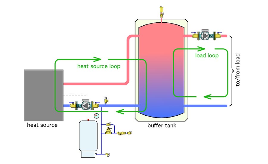
The heat source loop adds heat to the tank. The load loop removes heat from the tank. All heat must pass through the tank on its way from the heat source to the load.
This tank configuration has advantages and disadvantages. One advantage: The thermal mass of the water in the tank is well coupled to the heat transfer process. Another is the tank can provide excellent hydraulic separation between the heat source circulator and the load circulator.
One disadvantage is a cool buffer tank will definitely delay heat transfer from the heat source to the load. This is especially true if the water in the tank is well mixed due to turbulence or piping geometry that creates flow jets within the tank.
For years we designed systems around 4-pipe geometry. We just accepted the fact that a cool tank would delay heat transfer to the load. Then, we got involved with pellet boiler systems and I started investigating tank piping configurations used with these boilers in Europe.
One piping arrangement that appeared in several schematics was what I now call a “2-pipe” configuration. The main difference: The piping to the load is connected between the heat source and the tank, rather than downstream of the tank. Figure 2 shows a comparison between a 4-pipe and 2-pipe configuration.
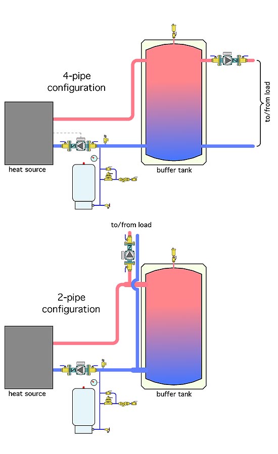
I’ll admit my first impression of the 2-pipe configuration was a mixture of confusion and perhaps cynicism that the Europeans who used this configuration were making a mistake. However, with more study, I became aware of two significant advantages of the 2-pipe configuration.
Advantage No. 1
The flow rate in and out of the tank is always the difference between the heat source flow rate and the load flow rate. Consider a situation where the flow rate through the heat source is 8 gpm, and at the same time, the flow rate through the load is 6 gpm. Under these conditions, the flow rate into and out of the tank would be 8-6 = 2 gpm.
So what? Why does this matter? The answer is based on a seldom-referenced thermodynamic concept called exergy, which is a way to quantify the usefulness of thermal energy.
Think of it this way: Imagine a huge “cube” of air outside your house that has measurements of 1 mile in all three directions. The air within that cube has a temperature of 40° F. If you could cool all that air down to say 0°, billions of Btu would be released. That’s a huge amount of energy. But if you needed that energy to maintain the inside of a building at 70°, not one of those billions of Btu is directly useful. The key word here is directly. Yes, you could use a heat pump to gather that “low grade” energy, but that’s not a direct use. I’ll spare you the math, but a thermodynamisist would say that the energy in the air has low exergy.
So what does that have to do with a buffer tank? The answer is stratification. A well-stratified buffer tank contains more useful thermal energy than another otherwise identical tank in which the water has the same average temperature, but less stratification due to mixing. Figure 3 shows a comparison.
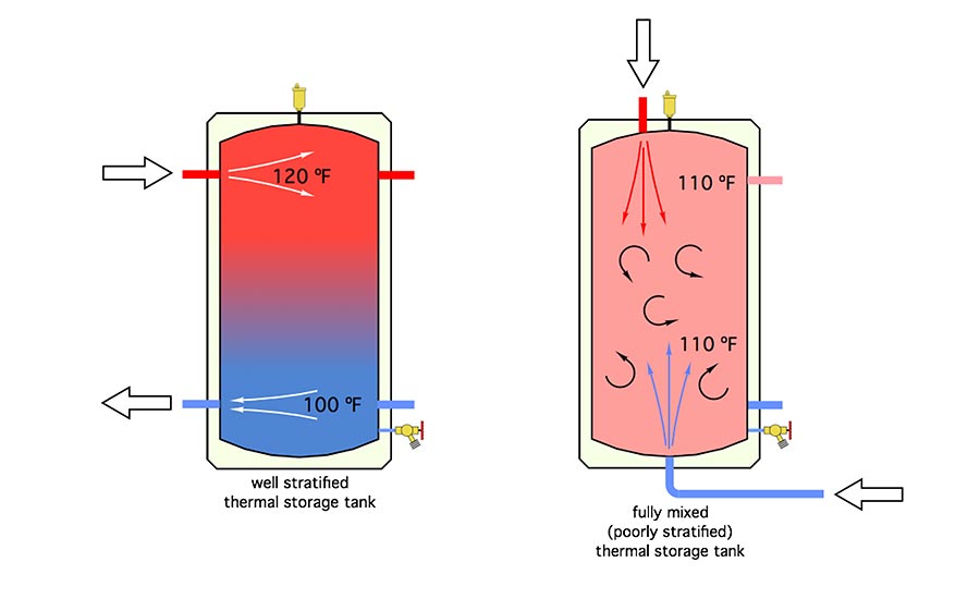
Assuming a symmetrical temperature profile from top to bottom, the well-stratified tank on the left has an average water temperature of (120+100)/2 = 110°. The tank on the right is fully mixed and also has an average water temperature of 110°. Assume both tanks have the same volume, and thus contain the same amount of heat. Now ask yourself the following question: Which tank could supply a load, at least for some time, requiring 115° water? Answer: Only the left tank.
Which tank could supply a load, at least for some time, requiring 111° water? Again, only the tank on the left. Even though both tanks initially contain the same amount of heat, the well-stratified tank holds that heat in a more directly useable form (e.g., some of the water at a higher temperature compared to the average temperature). The energy in the left tank has higher exergy than the energy in the right tank.
The take-away here is temperature stratification in a thermal storage tank is desirable and should be encouraged. One of the best ways to do so is to reduce flow velocity into the tank. The lower the entering flow velocity, the less mixing, and the better temperature stratification can be preserved. Thus, one underlying advantage of a 2-pipe configuration is that only the difference between the heat source flow rate and load flow rate passes through the tank.
Advantage No. 2
Because the load is supplied upstream of the tank, a 2-pipe configuration allows heat to move directly from the heat source to the load when both are operating at the same time. This greatly reduces any time delay in getting heat to the load at a time when the tank temperature is lower than normal.
Details matter
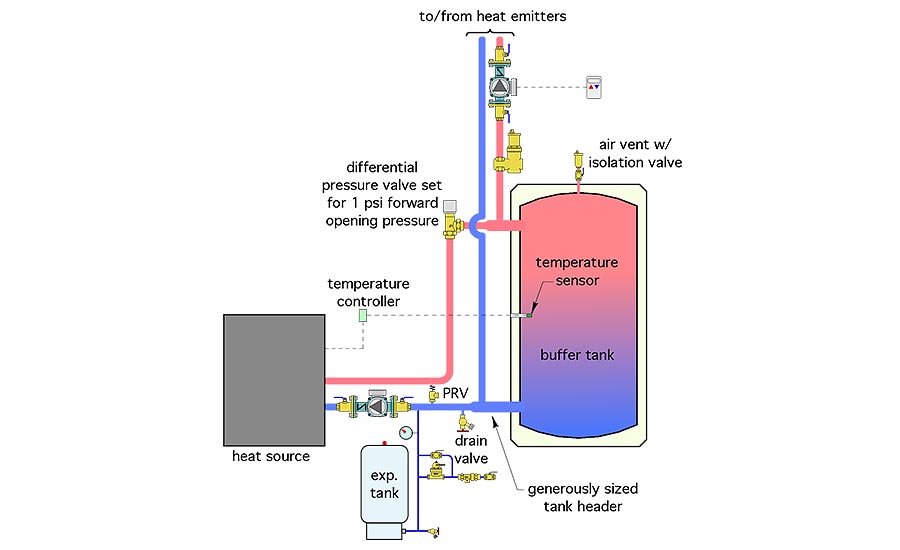
Now that you know the advantages, let’s look at the details needed for a successful 2-pipe buffer installation. The piping schematic in Figure 4 will be the reference.
Detail No. 1: Don’t allow flow returning from the load to pass through the heat source when it is off. Unlike a 4-pipe, or even a 3-pipe buffer tank, flow returning from the load has a choice of two flow paths when it returns to the lower tank header.
If the heat source is on, and the flow rate through it is equal to or greater than the load flow rate, all flow returning from the load will go through the heat source. If the heat source is on, and the flow rate through it is lower than the load flow rate, some of the flow returning from the load will go through the tank, while the rest goes through the heat source. No problem with either of these scenarios.
When the heat source is off, the desired condition is for all flow returning from the load to pass through the tank. However, if the flow path through the heat source is not blocked, some of the flow returning from the load will pass through it.
The percentage of the return flow passing through the inactive heat source depends on the hydraulic resistance of the flow path from the lower header through the heat source and back to the upper header. The higher the resistance of this flow path relative to that through the tank, the lower the percentage of return flow passing through the heat source.
Although flow passing through an inactive heat source doesn’t damage anything, it does cause increased heat loss to the mechanical room. It also reduces the supply water temperature to the load due to the two flow streams — one through the tank, and the other through the heat source —recombining at the upper tank header. Neither of these two conditions are desirable.
There are several ways to prevent flow passing through the inactive heat source. A motorized ball valve that only opens when the heat source is on, is one approach. It works, but is arguably more expensive than another option: The use of a differential pressure valve between the heat source and upper tank header, and setting it for a forward opening pressure of 1 to 1.5 psi.
The latter is typically the minimum differential pressure setting for these valves, and corresponds to the knob being screwed all the way out — minimizing the spring pressure holding the valve’s disc against its seat. A differential pressure valve also replaces the need for a check valve to prevent reverse thermosiphoning between the tank and heat source when the latter is off. The limitation with these valves is pipe size, they are currently only available in North America in sizes up to 1.25 inches.
One might consider the spring-loaded check valve cartridge found in many small circulators as another possibility. However, I’ve found that the 0.3 to 0.5 psi forward opening pressure typical of these valves is not sufficient to prevent flow through the heat source when it’s off. There are check valve inserts with stronger internal springs that can do this. Unfortunately they’re not currently available to end users in small quantities.
Detail No. 2: The tees that connect the load piping with the piping between the heat source and tank must be kept as close to the tank as possible. This minimizes the head loss through the tank headers, allowing the tank to provide good hydraulic separation of the two circulators. It’s also a good idea to increase the pipe size of the short tank headers to minimize head loss.
Detail No. 3: Control the heat source based on tank temperature, not room air temperature. This allows the heat source to keep operating after the space heating load is satisfied, and until the tank reaches its upper temperature limit. It will then be ready to immediately transfer heat to the load on the next call for space heating.
One method of control is a simple temperature setpoint controller that turns on the heat source when the temperature sensor in the tank drops to some preset value. The heat source continues to run until the temperature at the tank sensor climbs to some preset maximum value.
Another option is to control the temperature in the tank based on outdoor reset control. The warmer the outdoor temperature, the lower the average temperature of the buffer tank. The concept is to heat the water just hot enough to allow the heat emitters to meet the current heating load. This approach is especially advantageous when the heat source efficiency increases as the temperature of the fluid it is heating decreases. Mod/con boilers and heat pumps are both examples of such heat sources.
A potential problem associated with controlling the heat source based on room temperature occurs when the flow rate through the heat pump is close to the flow rate to the load. Under this condition, there will be very little flow through the buffer tank. This can leave the thermal mass of the tank “stranded.” If the room thermostat is satisfied the heat source shuts off regardless of the temperature of the buffer tank. There’s no point in using a buffer tank if the system doesn’t allow it to be properly “exercised.”
Miscellaneous details: Finally, be sure you include essential hardware, such as a central air separator, tank top air vent with isolation valve, adequately sized expansion tank, a valve that can be used to drain the tank if ever necessary and a pressure relieve valve.
Setting up a 2-pipe buffer based on these details will give you consistent performance, and improve the temperature stratification within the tank. Remember, exergy, as well as energy are terrible things to waste.
Looking for a reprint of this article?
From high-res PDFs to custom plaques, order your copy today!


