Ray Wohlfarth: Troubleshooting hydronic systems
Piping layout in hydronic systems is often confusing.
When troubleshooting a hydronic system, the piping layout is often confusing. To understand the system, I sometimes sketch the piping to help me visualize the flow of water. On a particularly complicated job, I will use colored highlighters to help me see the circulation in my mind. The following hydronic jobs were ones that did not work as intended.
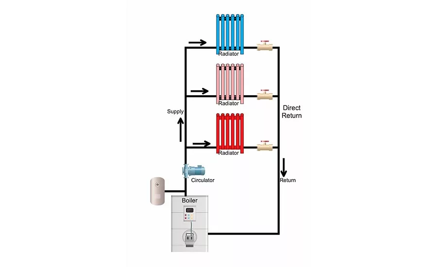
Direct return
The service call was at an old home with cast iron radiators. The customer said they had plenty of heat on the first floor, some heat on the second floor and no heat to the third-floor radiators.
“Oh, the Goldilocks and the Three Bears syndrome,” I said, laughing.
The owner looked at me like I had three eyes.
“Never mind,” I whispered.
My first thought was the system pressure was too low. It takes one pound of pressure to raise water 2.3 feet. The highest radiator was 36 feet above the boiler, which meant the system needed 16 psi, plus 3-4 psi as a safety factor.
The pressure on the PTA gauge read 25 psi, plenty of pressure. After sketching the piping, I realized it was a direct return hydronic system. A direct return system looks like a ladder, and the first radiator fed is the first to return, essentially short-circuiting the system. To avoid that, balancing valves are installed in the piping to restrict the flow through the closest radiators to force more flow to the ones further away.
The original installer used globe valves in the return piping to balance the flow. Someone opened the valve fully on the first floor, so most of the heat was going through those radiators. By closing the valve a few turns, the upper radiators started to heat. After balancing the system, all the radiators heated evenly. At that point, I removed the valve handles and took them to the basement.
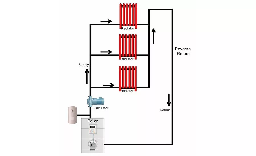
Reverse return
The reverse return piping system also resembles a ladder with the exception the radiators closest to the boiler are the last to return. The furthest radiator is the first to return. This makes the system almost self-balancing and assures equal heat to all the radiators. The cost to install this type of system is a bit more, as there is more piping. It is preferred over the direct return because you do not have to worry about balancing the system.
Zone valves
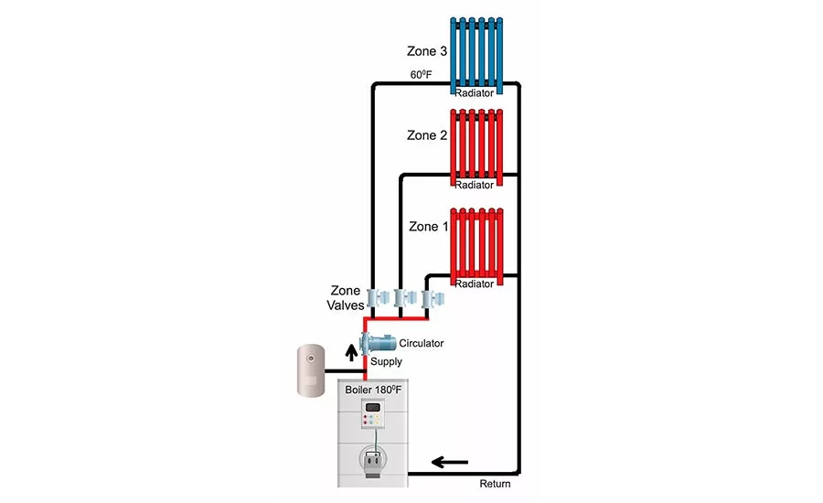
Shortly after installing zone valves in a church, the problems started. The installer believed zoning would save money for the parish. "Why heat the whole building when you only need to heat part of it during the week?" the installer asked.
The three zones consisted of the office, which was used seven days a week; the church, which was used an hour a day during the week for morning services and all weekend; and the last zone was the daycare, which was only used one day a week. Programmable thermostats were installed to lower the temperature during the unoccupied times. They set the unoccupied temperature for 60° F and the occupied temperature for 72°.
The first problem arose when the bearing assembly for the circulating pump failed, and they attributed it to the age of the pump. When the replacement bearing assembly failed a short while later, they realized there might be additional problems.
During the shoulder times of the year, the zones were satisfied quickly and closed the valves. The pump operated all the time during the heating season and only shut off when the outside temperature was above 60°. With the zone valves closed, this caused the pump to dead-head and destroyed the bearing assembly. Dead-heading means the pump is still running, but the valves are closed, and there is no flow going through the system.
To resolve the bearing problem, they controlled the pump operation with the end switches on the zone valves. The pump would only operate when there was a call for heat and a zone valve was open. The boiler would maintain 180°, ready for the next call for heat.
They were then introduced to thermal shock. Thermal shock occurs when cold return water meets the hot boiler water. It causes rapid expansion and contraction; damaging the boiler. During the unoccupied times, the room temperature was 60°, and so was the water in the piping. When the thermostat switched to occupied mode, the 60° water came rushing back to the 180° boiler water, and it was not a happy reunion. The thermal shock destroyed the boiler.
Most boilers are designed for a 20° to 30° temperature swing. In this case, the returning temperature was 120° lower than the boiler water temperature. To resolve the problem, a bypass pump and pipe was installed. The pipe was connected between the supply and return piping. The pump would inject hot supply water into the return piping to raise the temperature of the return water to be within 20° to 30° of the supply water temperature.
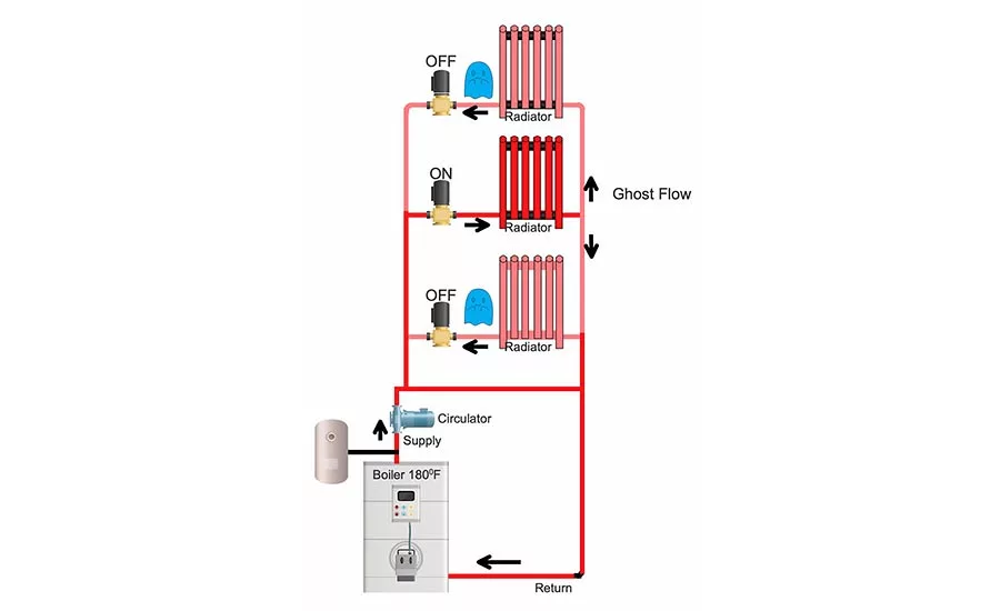
Ghost flow
Another customer was experiencing overheating of the idle zones. You could feel the heat in the radiators even though the circulator was off. Tracing the piping, I discovered the reason. The installer did not use flow control or check valves in the piping. When the circulator started on the zone calling for heat, the pump developed a pressure differential in the idle zones and caused the flow to migrate through the piping, which is referred to as ghost flow.
The repair was to install a flow control valve in the piping for each zone. I prefer using flow control valves rather than simple swing checks because they are a weighted check valve and only open when the pump starts.
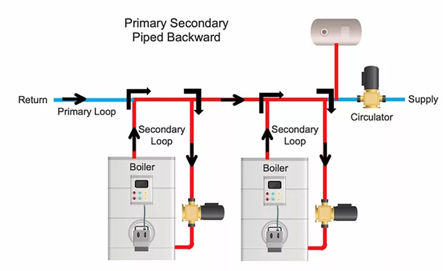
Backward piping
We were called to this project because the building was cold, although the boilers were hot. It was a primary-secondary piping system, and the supply and return piping were within 12 inches of each other on the system’s primary loop, but they were piped backward.
The boiler discharge pipe fed the warm water into the primary heating loop upstream of the boiler inlet piping. The already heated water was pulled back into the boiler, causing them to short cycle. The boilers were shutting off on the internal operating temperature control, but the loop was cold. The problem was repaired when the supply and return piping to each boiler was switched.
The bottom line is if you have a problem job, try drawing the piping layout to help troubleshoot the system.
Looking for a reprint of this article?
From high-res PDFs to custom plaques, order your copy today!


