The Glitch & Fix: March 2018
The Glitch:
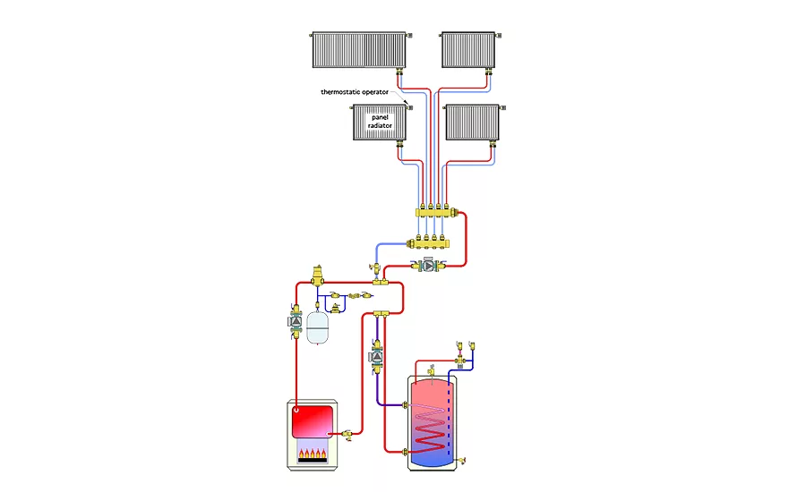
A hydronic system is to supply four panel radiators, each with their own thermostatic radiator valve, and an indirect water heater from a gas-fired sectional cast-iron boiler. The system is designed using primary / secondary piping as shown below. The primary circulator operates whenever the space heating load or the indirect water heater call for heat. All circulators are standard, fixed speed, wet rotor units.
a. Can you spot at least 6 details that are incorrect?
b. Beyond the incorrect details, are there ways to improve the design to provide the same functionality with fewer components?

The Fix:
Before looking at improvement, here’s a tally of the errors on the primary/secondary approach:
- The primary circulator is pumping toward, rather than away from the point of no pressure change (e.g. where the expansion tank connects to the system).
- The secondary circulators are both pumping toward, rather than away from the primary loop. This is incorrect because each secondary circuit “sees” the primary loop connection as its point of no pressure change (because the expansion tank is in the primary loop). Thus all secondary circulators should pump into their respective secondary circuits.
- The piping for the panel radiator sub-system is reversed at the closely spaced tees. This will cause a reduced supply water temperature to the panels.
- The heat exchanger coil within the indirect water heater is not piped for counterflow. The hot water should always enter the top connection of the coil.
- Assuming primary / secondary piping was used, the indirect tank should be the first load connected to the primary loop, and thus able to operate with the highest available water temperature.
- The purging valve is missing on the return side of the secondary circuit serving the indirect water heater.
- There is no thermal trap installed on the thermostatic tempering valve of the indirect tank. This will lead to thermosiphoning and wasted energy.
- There is no means of differential pressure control within the zoned secondary circuit serving the panel radiators.
- The lack of check valves in the secondary circulators will allow for heat migration. As shown, the indirect water heater will use its secondary circuit piping to continually dump heat to its surroundings.
The fix drawing shows what I consider to be an improved design that provides the same functionality. It eliminates one of the circulators and both sets of closely spaced tees required in the previous approach.
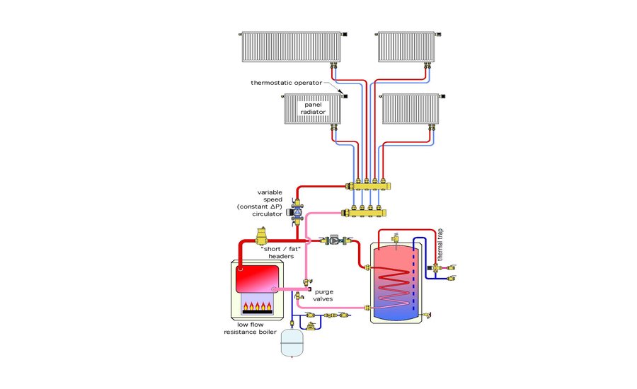
The loads do not require this to be a primary / secondary system. The low head loss boiler and generously sized header piping provide sufficient hydraulic separation between the two circulators, even when one of the loads operates with a variable speed circulator. Just keep the headers relatively short, and sized for a maximum flow velocity of 2 feet per second. This approach eliminates both the installation and operating cost of a primary circulator.
Another change is use of a pressured regulated constant ∆P circulator within the subsystem serving the panel radiators. This eliminates the need of a differential pressure bypass valve and significantly reduces operating cost compared to a fixed speed circulator. Today, it’s likely to be less expensive to install a pressure regulated circulator compared to a fixed speed circulator paired up with a differential pressure bypass valve. The operating cost will also be less than half that of an equivalent fixed speed circulator.
A thermal trap is shown on the piping leading to the thermostatic mixing valve on the indirect water heater.
Because of the very low hydraulic resistance of the boiler and headers it is possible to locate the system’s expansion tank on the inlet of the boiler where its temperature will remain a bit cooler, and thus its internal air pressure will be less effected by the elevated water temperature in the system.
Please click here to view The Glitch & Fix: March 2018 in pdf form.
Looking for a reprint of this article?
From high-res PDFs to custom plaques, order your copy today!


