The Glitch & Fix: January 2018
The Glitch:
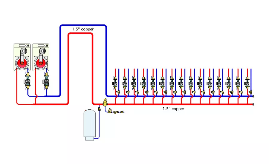
John Pughe is a long-time colleague of mine and a true hydronics professional. He recently sent me an “as installed” and “as corrected” schematic for a hydronic heating system with twin 200,000 Btu/hr mod/con boilers, and 15 zones, each powered by its own circulator. The “as installed” schematic is shown in figure 1.
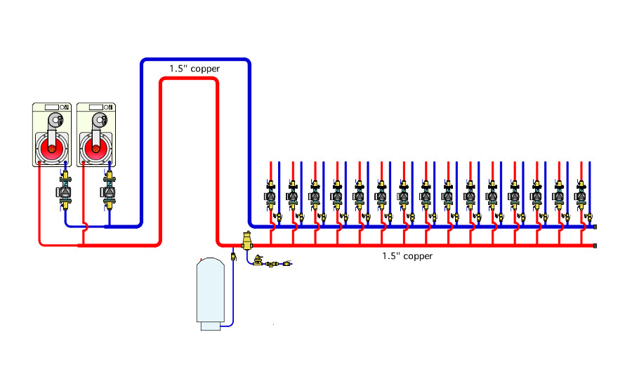
Figure 1
The system was not delivering sufficient heat to the last 6 or 7 zones on the far end of the 1.5” copper headers. It was also having problems with nuisance trips of the boiler low water cutoffs due to trapped air at high points in the piping between the boilers and distribution headers.
Can you spot several relatively simple and inexpensive details that would improve the situation? How about if you had the opportunity to design the system from scratch? What would you do differently?
The (first) Fix:
John quickly recognized one of the problems - the lack of hydraulic separation between the boiler circulators and zone circulators. This set up a combined flow distribution between the boiler circulators and the zone circulators on the left side of the undersized headers that “starved” the zones at the far right end of those headers.
He also recognized that the system contained a lot of expensive hardware, which made a complete do over impractical. He recommended installation of two closely spaced tees as shown in figure 2. That small change provided sufficient hydraulic separation of the circulators and solved the flow starvation problem in the far right zones.
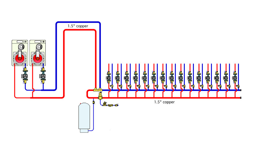
Figure 2
Other fixes:
Figure 3 shows my thoughts on how the system could be improved. This is certainly not the only way the system could be improved, but it does bring several contemporary hydronics system design concepts into the mix.
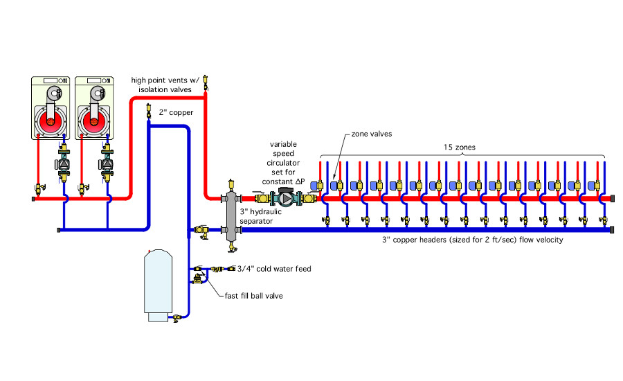
Figure 3
The two boilers drop into a short set of 2 inch headers that allow the full flow to enter the hydraulic separator at a flow velocity no higher than 4 feet per second. Each boiler can be isolated and purged.
The hydraulic separator provides high efficiency air and dirt separation as well as hydraulic separation of the boiler circulator from the single variable speed distribution circulator.
I included a couple of air vents with isolation valves at the piping high points to assist with initial air removal. I also specified a 3/4” make up water assembly to get a strong purging flow rate when needed.
The load side of the hydraulic separator connects to a set of 3 inch pipe size headers. That size allows the maximum flow velocity in the headers, with all zones operating, to not exceed 2 feet per second. Thus, there is very little head loss along the headers, which are still kept as short as possible. With good planning, the header would only have to be about 6 feet long. The locations where individual zones tap into the headers is almost irrelevant because of the very low head loss along the length of the header.
The high efficiency (ECM-based) circulator operates on a constant ∆P setting. It would be set for the required ∆P when all zones are on, and would automatically ramp its speed up and down as zone circuits open and close.
Assume that each zone valve costs about the same as a small zone circulator. Buying 15 zone valves would be about a wash with buying 15 zone circulators. Next, consider the savings of putting a full port ball valve on each side of the single distribution circulator versus 15 sets of isolation flanges on zone circulators. Also estimate the savings in line voltage wiring cost associated with one distribution circulator versus 15 zone circulators circulators.
Beyond hardware savings, consider the difference in operating cost over the life of the system. Although an estimate is subject to several assumptions about how the zones are operated, the power required by each zone circulator, and the time the variable speed circulator operates at different power levels, the saving in electrical energy over the life of the system is likely to be several thousands of dollars.
The “clean slate” design uses simple and repeatable concepts: Hydraulic separation, “short / fat” headers, variable speed circulation, efficient air and dirt removal. It’s likely to be less expensive to install and significantly less expensive to operate compared to the “as found” situation we began with.
Please click here to view in pdf form.
Looking for a reprint of this article?
From high-res PDFs to custom plaques, order your copy today!


