When is flow reversal practical?
Increasing heat output.

Formula A. Since the secondary circuit load removes 40,000 Btuh of heat, this is the temperature drop in the secondary circuit. Photo credit: John Siegenthaler
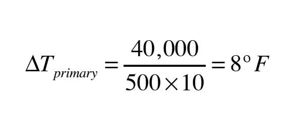
Formula B. Hence, this is the temperature drop in the primary loop. Photo credit: John Siegenthaler
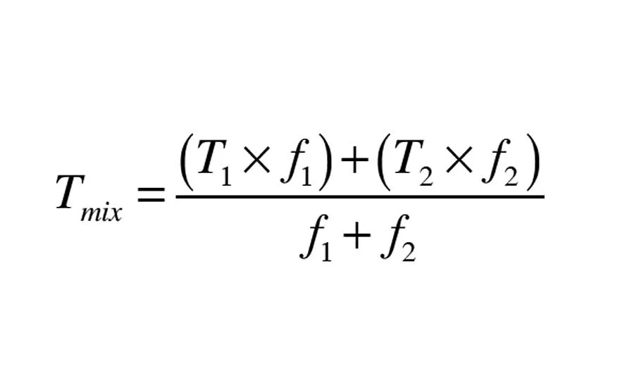
Formula 1. In this formula, f1 and f2 are the flow rates of the two streams being mixed, and T1 and T2 are the temperatures of these streams as they enter the mixing point. Photo credit: John Siegenthaler
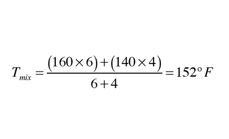
Formula C. T2 and f2 are the temperature and flow rate of the secondary circuit return (T2 = 140°F, and f2 = 4 gpm). Putting these numbers into the mixed-stream formula yields this. Photo credit: John Siegenthaler
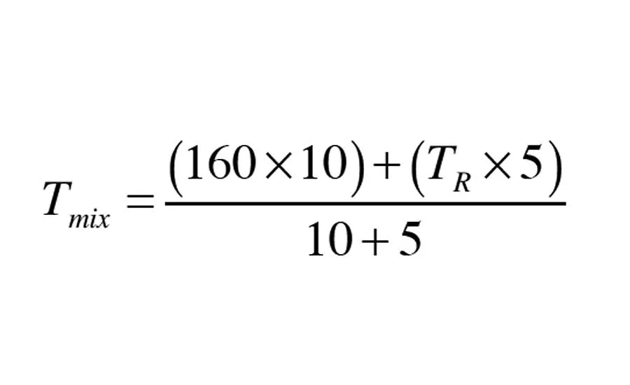
Formula 2. We can’t solve Formula 2 by itself because we don’t know the value of the return temperature from the secondary circuit (TR). Photo credit: John Siegenthaler

Formula D. With all other conditions remaining equal, the heat output of typical residential fin-tube baseboard increases with increasing flow rate as in Formula D. Photo credit: John Siegenthaler
Formula E. Thus, the theoretical change in heat output based on increasing flow through the baseboard from 4 to 15 gpm, with all other conditions remain the same would be Formula E. Photo credit: John Siegenthaler
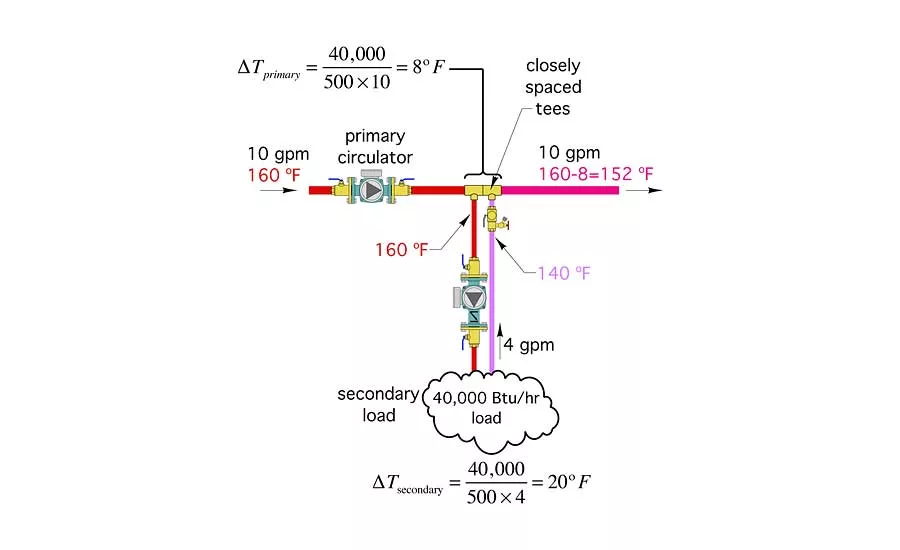
Figure 1. The best way to predict the output of a situation such as that shown in Figure 1 where multiple energy flows converge. Photo credit: John Siegenthaler

Figure 2. An even more interesting result is what happens to temperatures and heat transfer in the secondary circuit. Photo credit: John Siegenthaler
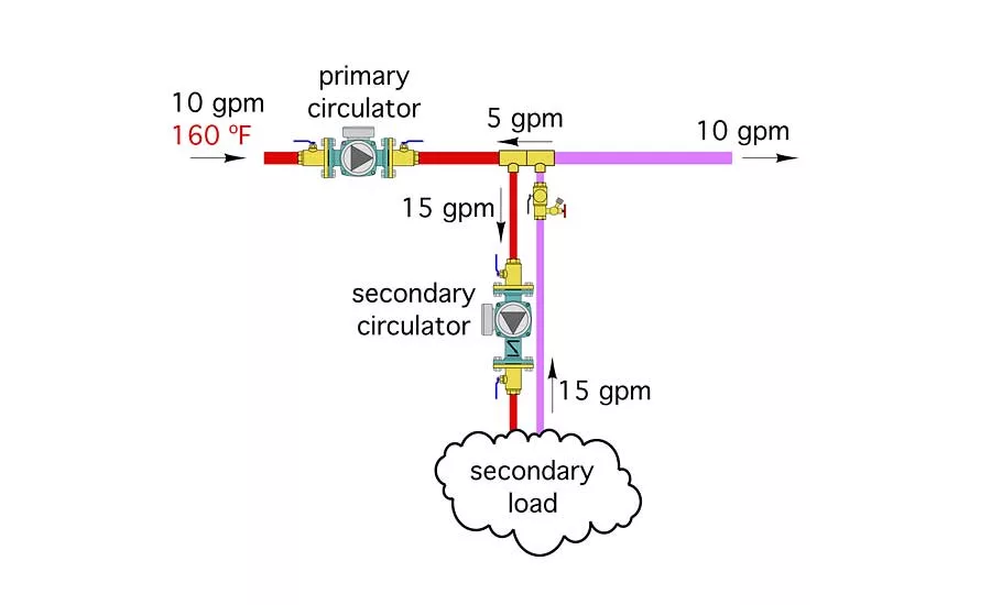
Figure 3. Suppose a circulator capable of generating a flow rate of 15 gpm was installed in the secondary circuit. Figure 3 shows the situation. Photo credit: John Siegenthaler
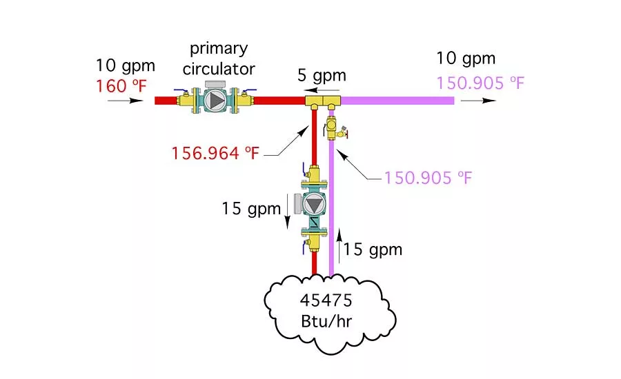
Figure 4. The results will give both the mixed supply water temperature and the return temperature from the baseboard. These results are shown in Figure 4. Photo credit: John Siegenthaler
The North American hydronics industry has dealt with primary/secondary piping systems for years. Most hydronic heating pros know the principles used in these systems.
Still, based on questions I’ve had over the years, it’s evident that some aspects of primary/secondary coupling of circuits remain “mysterious.” One of the common questions is, “What happens if the flow rate in the secondary circuit is greater than the flow rate in the primary circuit?” Other questions related to the same concept include:
-
If reverse flow between the tees did occur, would it cause damage or interfere with other parts of the system?
-
If reverse flow between the tees did occur, how would it affect the heat output from the secondary circuit?
The concept of flow reversal runs counterintuitive to the idea of a single primary loop supplying heat to several secondary loops.
It’s easy to conceptualize a primary circulator as having to produce enough flow to “feed” all the operating secondary circulators. Fortunately, this is not true.
Although the primary loop does supply heat to each secondary circuit, it does not supply flow to each secondary circuit. Supplying heat to a secondary circuit is evidenced by a drop in temperature of the primary loop flow as it passes a pair of closely spaced tees. This is entirely different from supplying flow to the secondary circuit. In animated terms, the primary circulator doesn’t even know that the secondary circuits exist and vice versa. Each circulator operates as if the circuit in which it is installed is completely isolated from the other circuits.
When P > S: Let’s look at a typical system in which a primary loop serves a secondary circuit having a design load of 40,000 Btuh. Assume the primary loop flow rate is 10 gpm and that the water arriving at the first tee (of the closely spaced pair of tees) is at 160°F. Also assume that the circulator/piping design used for the secondary circuit allows a flow rate of 4 gpm to develop. Here is a close up of the situation along with the calculations for temperature drops.
Follow the Energy: The best way to predict the output of a situation such as that shown in Figure 1 (see above), where multiple energy flows converge, is to account for all energy carried in and out of the process.
Just as the flow rate of water into and out of a tee must balance, the energy carried into a mixing point must equal the energy carried out of that point. This is required by the first law of thermodynamics, which states that energy can neither be created nor destroyed — only exchanged.
Since the secondary circuit load removes 40,000 Btuh of heat, the temperature drop in the secondary circuit is (see Formula A above).
Hence, the temperature returning from the secondary load at design conditions is 160 – 20 = 140°F.
The temperature drop along the primary loop can also be determined by accounting for the fact that heat is being removed at the primary/secondary interface at a rate of 40,000 Btuh. Hence, the temperature drop in the primary loop is (see Formula B above).
Some of you may be wondering why the temperature drop in the primary loop is different from the drop in the secondary loop. It’s because of the different flow rates in these circuits (10 gpm in the primary circuit and 4 gpm in the secondary circuit). Heat transfer into or out of a fluid stream is always based on the multiplication of flow rate and temperature drop.
It’s also possible to calculate the water temperature leaving the downstream tee by applying the “mixed stream formula,” which is also based on conservation of thermal energy at a mixing point: Formula 1 (see above).
In this formula, f1 and f2 are the flow rates of the two streams being mixed, and T1 and T2 are the temperatures of these streams as they enter the mixing point. In the situation being analyzed, the mixing point is the downstream tee. There is a bypass flow from the upstream to the downstream tee of 6 gpm at 160°F. So T1 = 160°F and f1 = 6 gpm. T2 and f2 are the temperature and flow rate of the secondary circuit return (T2 = 140°F, and f2 = 4 gpm). Putting these numbers into the mixed-stream formula yields (see Formula C above).
When S > P: Suppose a circulator capable of generating a flow rate of 15 gpm was installed in the secondary circuit. Figure 3 shows the situation.
Notice that flow between the closely spaced tees has reversed. The 5 gpm flow rate is simply the primary loop flow rate minus the secondary loop flow rate. This flow reversal does not damage the system in any way.
Also notice that the flow rate in the primary loop, for all practical purposes, does not change. Why? Because the insignificant pressure drop between the closely spaced tees effectively prevents the primary loop from “feeling” a change in its hydraulic resistance. Remember, the primary loop doesn’t even “know” the secondary circuit exists.
An even more interesting result is what happens to temperatures and heat transfer in the secondary circuit. Again, we have to follow the energy into and out of the tees to predict what will happen.
The flow reversal between the tees now creates a mixing point at the upstream tee. Just the opposite of what occurred in the first scenario where the mixing point was at the downstream tee.
This mixing point will reduce the water temperature supplied to the secondary circuit. How much? Just use the mixed-stream formula again.
Formula 2 (see above).
Where:
Tmix= supply temperature to the secondary circuit (°F)
TR = return temperature from the secondary circuit (°F)
We can’t solve Formula 2 by itself because we don’t know the value of the return temperature from the secondary circuit (TR). We can, however, dig deeper based on some theoretical models of how the heat output of fin-tube baseboard changes with flow rate.
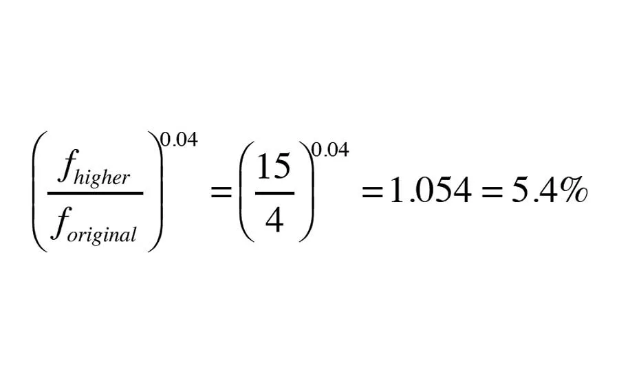
With all other conditions remaining equal, the heat output of typical residential fin-tube baseboard increases with increasing flow rate as follows (see Formula D above).
Where:
f = flow rate through baseboard (gpm)
Thus, the theoretical change in heat output based on increasing flow through the baseboard from 4 to 15 gpm, with all other conditions remain the same would be (see Formula E above).
Unfortunately, not all other condition will remain the same (for example, we already know there’s going to be mixing at the upstream tee that will reduce the supply water to the baseboard).
This is where the math gets messy. Suffice it to say that there is something called an iterative solution to this math. The results will give both the mixed supply water temperature and the return temperature from the baseboard. These results are shown in Figure 4.
Where does this leave us?
We’ve conceptually installed a larger secondary circulator in the secondary circuit and created reverse flow between the closely spaced tees. The net effect of the higher flow rate is an increase in heat output from the baseboard from 40,000 to about 45,475 Btuh. The increased heat output happens because the average water temperature in the fin-tube element is 150°F when the secondary circuit operates at 4 gpm, and increases to 153.93°F when that circuit operates at 15 gpm. The higher the average water temperature in the baseboard, the greater its rate of heat output.
Keep in mind that this is a conceptual discussion and doesn’t represent conditions that would necessarily make sense. For example, it’s not a good idea to operate a 3/4-inch fin-tube element at 15 gpm flow rate — doing so would result in erosion of the copper tubing. It would also require a circulator with a much higher input wattage and, thus, a much higher lifecycle operating cost. In theory, the power input to the circulator would have to increase more than 52 times! Is that practical? Of course not.
We’ve seen that flow reversal is possible in a P/S system. We’ve also seen that it can produce results that might not be intuitive (e.g., in this specific case, an increase in heat output from the secondary circuit). However, the power demand of operating a secondary circuit at 15 gpm rather than 4 gpm would far outweigh the slightly higher heat output.
The takeaway: It’s not good to increase heat transfer by significantly increasing flow rate through the heat emitters. If more heat output is needed, either increase the supply water temperature or add more heat emitter surface area — and keep flow rates reasonable.
This article was originally titled “Increasing heat output” in the January 2017 print edition of Plumbing & Mechanical.
To read the article in pdf form, please see here.
Looking for a reprint of this article?
From high-res PDFs to custom plaques, order your copy today!


